| Quantity | 3+ units | 10+ units | 30+ units | 50+ units | More |
|---|---|---|---|---|---|
| Price /Unit | $29.88 | $29.27 | $28.36 | $27.14 | Contact US |
 H2MD DC24-120V 6A Engraving Machine CNC Stepper Motor Driver Module Support Phase Dislocation Protection
$45.54
H2MD DC24-120V 6A Engraving Machine CNC Stepper Motor Driver Module Support Phase Dislocation Protection
$45.54
 ZM-3H2080 24V High Performance 3-Phase Stepper Motor Driver Controller AC80-220V for 86-130MM Stepper Motors
$166.32
ZM-3H2080 24V High Performance 3-Phase Stepper Motor Driver Controller AC80-220V for 86-130MM Stepper Motors
$166.32
 ZM-3H2080 12V High Performance 3-Phase Stepper Motor Driver Controller AC80-220V for 86-130MM Stepper Motors
$166.32
ZM-3H2080 12V High Performance 3-Phase Stepper Motor Driver Controller AC80-220V for 86-130MM Stepper Motors
$166.32
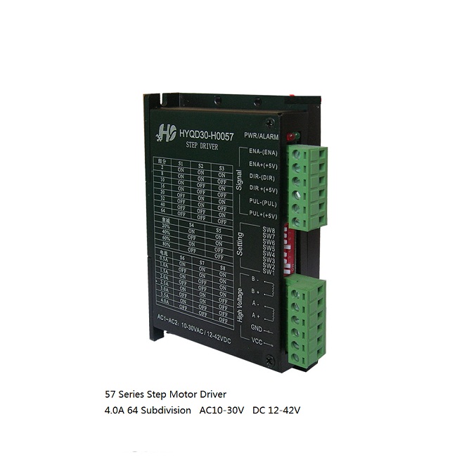
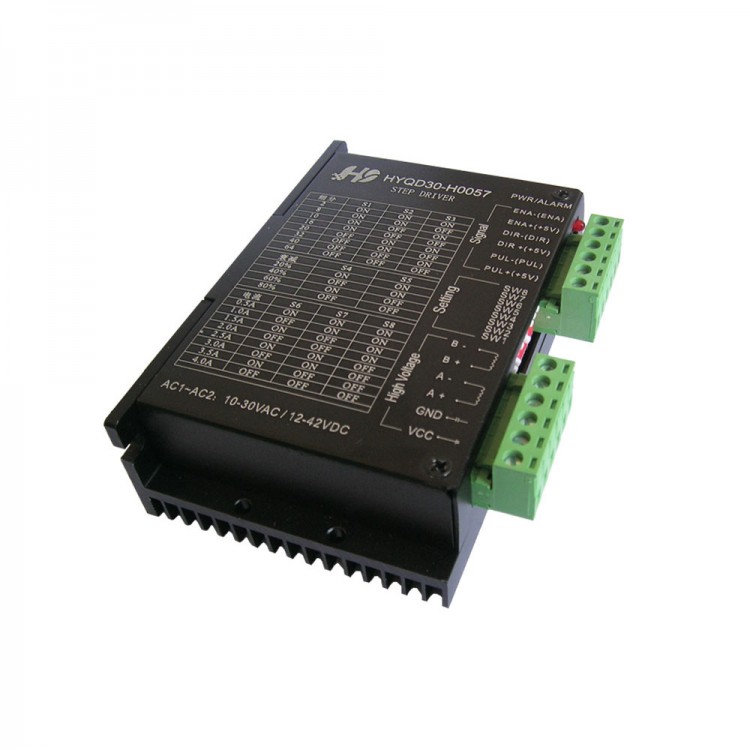
Brief introduction:
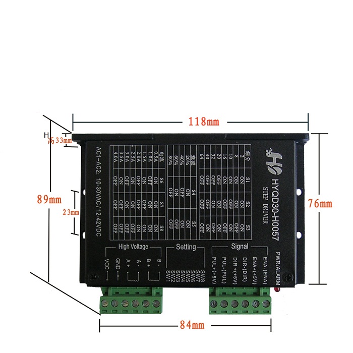
HYQD30-0057 It is a professional two-phase stepper motor driver.Reversing control can be achieved by 3 Location DIP switch, select 8Files subdivision control(2,8,10,16,20,32,40,64).By 3DIP switch option, Choose 6File current control (0.5A,1A,1.5A,2A,2.5A,3A, 3.5A, 4A). Suitable for driver 57,42,86 Two - Phase, four-phase hybrid stepping motor. To achieve low vibration, low noise, high speed drive motor effects.
- Dimension:118x76x33(mm)
Features:
- Power supply suitble for AC & DC with anti-reverse function
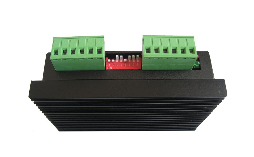
- Current generated by DIP switch selectable
- Interface with high-speed optocoupler isolation
- Eight kinds of adjustable subdivision
- Automatic semi-flow
- High integration and high reliability
- Anti-high-frequency interference ability
- Maximum pressure DC 50V
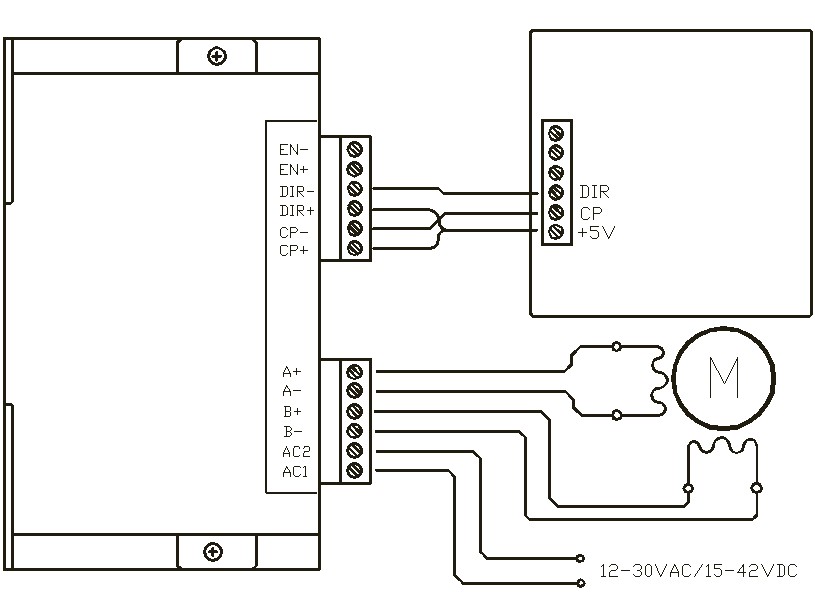
Input and output terminals Description:
The signal input terminal
CP +: Pulse signal input positive terminal.
CP-: Pulse signal input negative terminal.
DIR+:motor positive,reversing rotation control positive terminal.
DIR-:motor positive,reversing rotation control negative terminal.
EN +: Motor offline control the positive terminal.
EN-: Motor offline control the negative terminal.
Motor winding connection:
A +: Connect the motor windingsA +Phase.
A-: Connect the motor windingsA-Phase.
B +: Connect the motor windingsB +Phase.
B-: Connect the motor windingsB-Phase.
Working power connection:
AC1~AC2 connect power:range:AC12-30V,DC15-42V,you can not surpass the range,or the driver can not work normally,even damage the machine.
To ensure the best working status,recommend DC power voltage 24-36V,AC power voltage 18-30V.
Note:Please cut off the power when connecting cable.You can not phase dislocation,It may cause in-phase or Interphase short circuit and damage driver.
The input wiring instructions:
There are three-way input signal, they are: pulse signalCP +,CP-; direction level signalDIR +,DIR- off signalEN +,EN-. Input signal interface has two configurations: the user can employ a total of Yang needed Pole connection or common cathode connection.
Common anode connection: respectively, connect CP +,DIR +,EN + to the control system of the power supply, if This power is+ 5VIt can directly access, if this power is greater than+ 5VIt shall be an additional external current limiting resistor R, Guaranteed to drive internal optical coupling provided8-15mADrive current. Pulse input signal CP-Access,
Common cathode connection: respectively,CP-,DIR-,EN-Connected to the control system of the ground terminal; pulse input signalCP +Access direction signalDIR +Access enable signalEN +Access. For current limiting resistor, current limiting resistorRThe connection of the same values and common anode connection
Note:EN can be disconnected,EN is effective, rotor is in a free state (offline), then you can manually rotate the motor shaft, make it fit your adjustment. After manual adjustment is completed, and then make EN an inactive state in order to continue automatic control
When Drive controller and wiring, motors, power supply to common anode connection,Please disconnect the power wiring, motor wiring should pay attention not to the wrong, the inner phase phase short circuit, so as not to damage the drive.
Synchronous rectification:
By the DIP switch S1 selecting,when PWM is off, motor coil will remain some of the electromotive force.You can choose from an external Schottky diode to release remaining emf; you can also choose an appropriate timeCarved open simultaneously two lower legmosfetTo free EMF.S1PutONWhen openSRFunction, choose to open the two lower leg at the appropriate timemosfetTo release the force.S1 switch is OF, close the SR function, the Schottky diode connected externally to release the force.
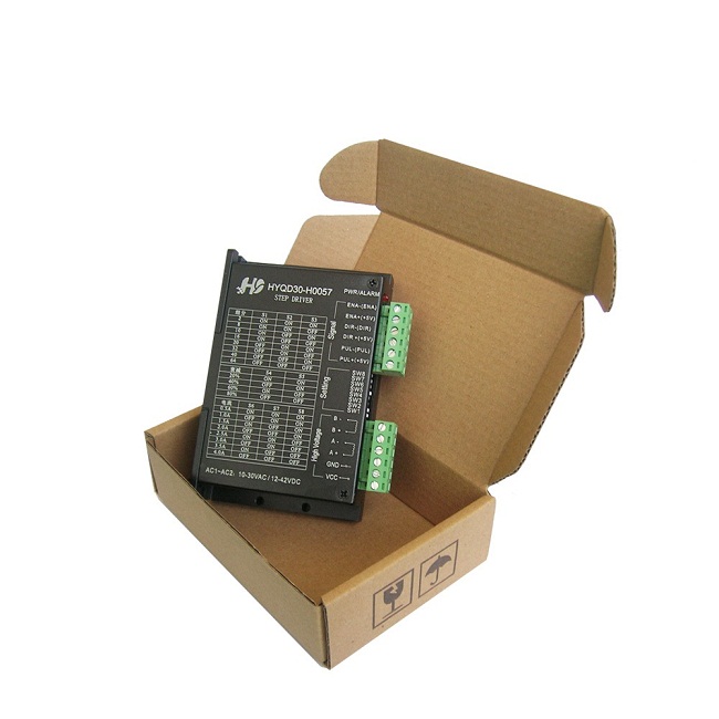
Package included:
- 1 x Step Driver