| Quantity | 3+ units | 10+ units | 30+ units | 50+ units | More |
|---|---|---|---|---|---|
| Price /Unit | $23.51 | $23.03 | $22.31 | $21.35 | Contact US |
 H2MD DC24-120V 6A Engraving Machine CNC Stepper Motor Driver Module Support Phase Dislocation Protection
$45.54
H2MD DC24-120V 6A Engraving Machine CNC Stepper Motor Driver Module Support Phase Dislocation Protection
$45.54
 ZM-3H2080 24V High Performance 3-Phase Stepper Motor Driver Controller AC80-220V for 86-130MM Stepper Motors
$166.32
ZM-3H2080 24V High Performance 3-Phase Stepper Motor Driver Controller AC80-220V for 86-130MM Stepper Motors
$166.32
 ZM-3H2080 12V High Performance 3-Phase Stepper Motor Driver Controller AC80-220V for 86-130MM Stepper Motors
$166.32
ZM-3H2080 12V High Performance 3-Phase Stepper Motor Driver Controller AC80-220V for 86-130MM Stepper Motors
$166.32
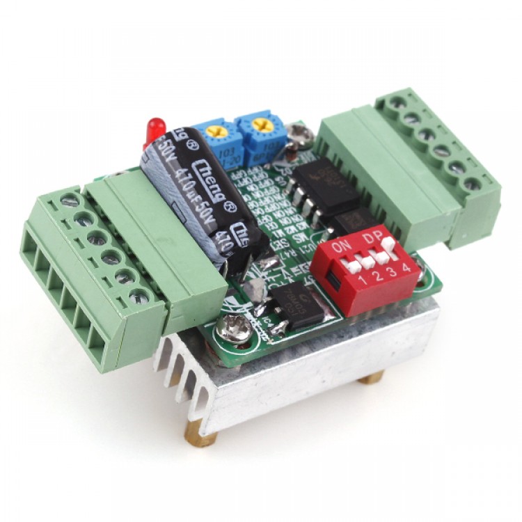
CNC THB6128 DC9-32V 2.2A Stepper Motor Driver Board
Descriptions:
1,Support full step, 2,4,8,16,32,64,128 of 8 kinds of sub-modes.
| M1 | M2 | M3 | subdivision |
| L | L | L | 1 |
| H | L | L | 1/2 |
| L | H | L | 1/4 |
| H | H | L | 1/8 |
| L | L | H | 1/16 |
| H | L | H | 1/32 |
| L | H | H | 1/64 |
| H | H | H | 1/128 |
The above settings, L represents the DIP switch to the ON position, H represents the DIP switch to the OFF position.
(Note: In a subdivision setting, the speed and the intensity is the highest, 1/128 setting is the speed of the lowest and most stable)
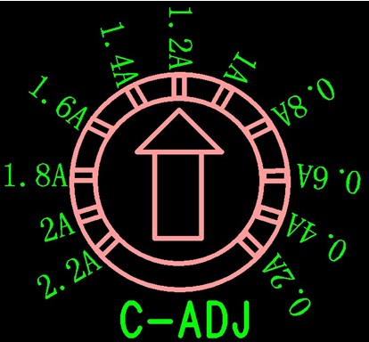
2,Maximum output current of 2.2A, 2A can fit within a variety of two-phase mini stepper motor, the current 0.2-2A stepless, any setting. Potentiometer is stepless current tick marks are for general reference. If your motor is transferred to 0.4A and 0.5A to 0.6A can be in the middle of the scale.
3,Input voltage is DC9-32V. Equipped with power indicator.
4,Power supply input circuit with anti-reverse design, more secure.
5,Automatic semi-flow on / off function, work more diverse. M4 is set for the switch.
6,There decay mode control functions. In matching different types of stepper motors can be controlled in different ways of working, the motor work more stable, noise, vibration to a minimum. LED indicators for the location near the potentiometer setting. Match the motor, adjust the potentiometer so that the motor can be minimal vibration and noise.
7,Industry-standard input and output interfaces, compatibility, can support common cathode or common anode connection.
8,With a large heat sink, with fixed columns, screws, easier to use.
Note: 1. Match the power drive must have a capacity of at least 2A or more. Otherwise unstable.
2. AB phase motor wires shall not cross pick, or burning drive.
3. When used with PLC, to add around 2K series limiting resistor, or burning drive.
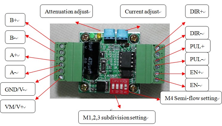
Terminal Description:
Signal input:
⑴ PUL + / CLK +: pulse signal input positive terminal.
⑵ PUL-/CLK-: pulse signal input negative terminal.
⑶ DIR + / CWW +: motor forward and reverse control positive terminal.
⑷ DIR/-CWW-: motor forward and reverse control negative terminal.
⑸ EN (A) / FREE +: motor off control positive terminal.
⑹ EN (A) / FREE-: motor off control negative terminal.
Motor winding connection:
⑴ A + / OUT1A: A phase motor winding connection.
⑵ A-/OUT2A: A-phase motor winding connection
⑶ B + / OUT1B: Connect the motor winding B phase.
⑷ B-/OUT2B: Connect the motor winding B-phase.
Special Note: Do not (1) (3) or (2) (4) cross-coupled motor cable, the drive will burn. When debugging, the best connected motor line, measured with a multimeter drive terminals: A +, A-are interlinked, B +, B-are interlinked. A + and B + is not the same, so as to power test machine.
Operating voltage connection:
⑴ V + / VM: Connect the DC power supply positive.
⑵ V-/GND: Connect the DC power supply negative.
Package List:
- 1*THB6128 Driver Board