| Quantity | 3+ units | 10+ units | 30+ units | 50+ units | More |
|---|---|---|---|---|---|
| Price /Unit | $18.52 | $18.14 | $17.58 | $16.82 | Contact US |
 0-10V/0-25mA 4-Channel Current Voltage Signal Generator Brightness Adjustable LED Signal Collector with 35MM DIN-Rail Base
$20.52
0-10V/0-25mA 4-Channel Current Voltage Signal Generator Brightness Adjustable LED Signal Collector with 35MM DIN-Rail Base
$20.52
 0-10V/0-25mA 4-Channel Current Voltage Signal Generator Module Brightness Adjustable LED Signal Collector
$18.57
0-10V/0-25mA 4-Channel Current Voltage Signal Generator Module Brightness Adjustable LED Signal Collector
$18.57
 Automobile Crank Shaft Synchronization Signal Simulator Module 6-Channel Output Signal Generator Module with LED Display
$64.45
Automobile Crank Shaft Synchronization Signal Simulator Module 6-Channel Output Signal Generator Module with LED Display
$64.45
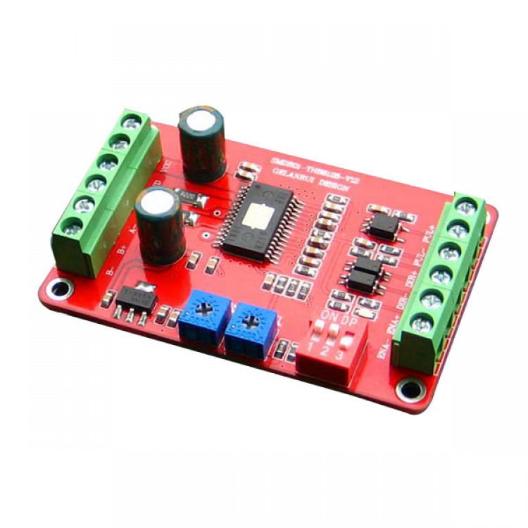
THB6128 Stepper Motor Driver Driver Board 128 Microstep 2A Current 28 39 42 57 Motor
Feature:
- Average current control, two-phase sinusoidal output current drive
- DC 9 ~ 32V power supply
- High-speed optical isolation signal input interface
- Overvoltage, undervoltage, overcurrent, short circuit protection
- 8 file subdivision (1/2/4/8/16/32/64/128) and automatic half current function
- Output phase current setting stepless adjustable 0-2A
- Decay mode adjustable to adapt more motor
- Start high speed, high-speed torque
- Has a power indicator light, set aside four bolt holes for easy installation;
- Module size: 4.5cm '' 7.0cm '' 1.6cm;
插入三张表格图片
- Note : VCC is 5V , R is short ;
- VCC is 12V , R is 1K ~ 1.2K, 1/8W greater resistance ;
- VCC is 24V , R is 2.7K ~ 3.3K, 1/8W greater resistance ;
- R must be connected to the controller signals the end .
Motor winding connection
- A +: A phase motor winding connections .
- A-: A- phase motor winding connection
- B +: Connect the motor winding B phase .
- B-: B- phase motor winding connections .
- Note: Do not cross-connect A and B , will burn drive. After debugging , best take a good electrical lines, measured with a multimeter drive terminals : A +, A- are interlinked , B +, B- are interlinked. A + and B + is not the same, so as to power on the test machine .
Power cable
- VCC: connect the positive DC power supply voltage DC 9 ~ 32V, recommended 12 or 24V.
- GND: Connect the DC power supply negative .
- Note : The drive requires a power supply output capacity of more than 2A , the power cord can not reverse .
Three electrical parameters:
- Input voltage : DC 9V ~ 32V
- Input Current : 0.01A ~ 2.2A
- Output Current : 0A ~ 2.2A
- Working temperature: -20 ~ 60
- Storage temperature: -40 ~ 80
- Humidity : not condensation, can not have water droplets
- Atmosphere : the prohibition of combustible gases and conductive dust