| Quantity | 3+ units | 10+ units | 30+ units | 50+ units | More |
|---|---|---|---|---|---|
| Price /Unit | $10.37 | $10.16 | $9.84 | $9.42 | Contact US |
 H2MD DC24-120V 6A Engraving Machine CNC Stepper Motor Driver Module Support Phase Dislocation Protection
$45.54
H2MD DC24-120V 6A Engraving Machine CNC Stepper Motor Driver Module Support Phase Dislocation Protection
$45.54
 ZM-3H2080 24V High Performance 3-Phase Stepper Motor Driver Controller AC80-220V for 86-130MM Stepper Motors
$166.32
ZM-3H2080 24V High Performance 3-Phase Stepper Motor Driver Controller AC80-220V for 86-130MM Stepper Motors
$166.32
 ZM-3H2080 12V High Performance 3-Phase Stepper Motor Driver Controller AC80-220V for 86-130MM Stepper Motors
$166.32
ZM-3H2080 12V High Performance 3-Phase Stepper Motor Driver Controller AC80-220V for 86-130MM Stepper Motors
$166.32
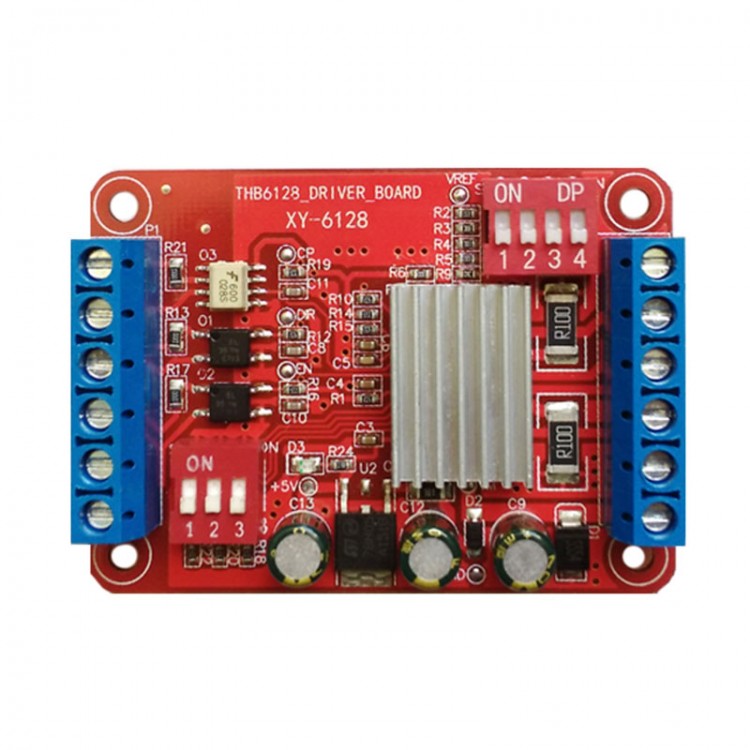
Stepper Motor Driver Board Control Module 2A 128 Subdivision THB6128 Driver Board
Description:
This module is based on original imported stepper motor drive chip THB6128 design. It can drive 57 and the following two-phase four-wire stepper motor.
Features:
- Using double full-bridge MOSFET driver, low on-resistance Ron = 0.55Ω
- Withstand voltage up to 36V, peak current 2.2A, continuous current 2A. Current can be set by dip switch
- 1, 2, 4, 8, 16, 32, 64, 128 a variety of subdivision for option. Subdivided through the DIP switch to set
- With automatic half-current locking function, chip greatly reduces heat generated when your motor is locked
- The chip with built-in over-temperature and over-current protection
- Built-in 5V logic signal supplies regulator chip, and adds current limiting resistor to reduce the heat by the chip when it inputs high voltage
- Input reverse connection protection
- Reasonable layout, clear identification, reliable and stable performance
Module Schematic Diagram: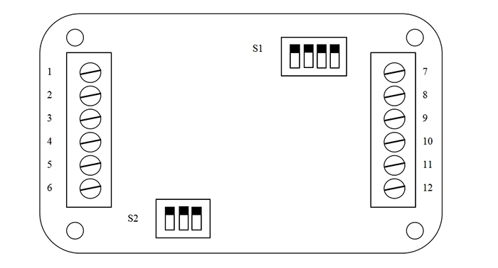
1. CP+: Pulse positive input
2. CP-: Pulse negative input
3. DIR+: Direction positive input
4. DIR-: Direction negative input
5. EN+: Enable positive input
6. EN-: Enable negative input
7.B-: Motor B phase negative output
8.B+: Motor B phase positive output
9.A-: Motor A phase negative output
10.A+: Motor A phase positive output
11.Power supply -
12.Power supply +
Signal Interfaces:
The module has three sets of input signals, namely CP pulse signal, DIR direction signal, and EN enable signal. The electrical diagram of signals inside the board is as follows: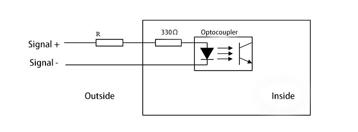
When external signal amplitude is 3.3-5V, the current limiting resistor R may not be connected. When signal amplitude exceeds 5V, input signal must be current limited to ensure that the input current of optocoupler is 8mA-15mA. Specific calculation method: On-voltage drop of optocoupler is generally about 1.1-1.3V, we get 1.2V, so the optocoupler's current = (voltage amplitude-optocoupler on-voltage drop 1.2V) / (R + 330)
Attention: If the operating current of optocoupler exceeds 20mA, the life of the optocoupler will be greatly reduced.
Characteristics of Input Signal Interfaces: Users can use common anode connection or common cathode connection as needed.
1.Common Anode Connection Method: Connect CP +, DIR +, EN + to the power supply of your control system respectively. Input signal is input through CP-, DIR-, EN-, and works at low level.
2.Common Cathode Connection Method: CP-, DIR-, EN- are connected to the ground of control system (SGND, isolated from power ground), input signal is input by CP +, DIR +, EN +, and works at high level.
Subdivision Settings:
Subdivision is set by dip switch S2, as shown in the figure below: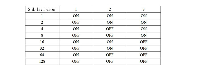
Generally, stepping angle of hybrid two-phase stepping motor is 1.8°, which means that the whole step of a single turn is 360 / 1.8 = 200 steps, then the number of pulses per turn is 200 * n, and n is the number of subdivisions.
For example, using 16 subdivisions, the number of single-turn pulses is 200 * 16 = 3200, that is, 3200 pulses are input from CP, and stepper motor rotates a full circle.
Current Settings:
This module uses resistor divider to provide reference voltage to the chip's VREF pin, and select resistors through dip switch S1. The definition is as follows: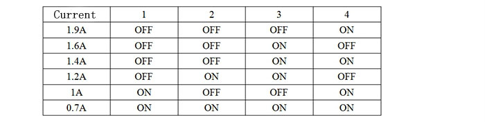
It lists common combinations of current-level DIP switches, and the other combinations can achieve other phase current settings. Specifically, it can be calculated by measuring voltage at the test point Vref.
Calculation Formula:
When your motor operates, motor phase current = Vref * 2
When your motor is locked, due to half-current locking, Vref is also automatically halved, and motor phase current = Vref * 4
Current Attenuation Method: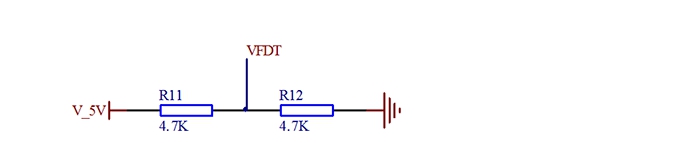
The module uses two 4.7K resistors. Set the voltage of VFDT pin to 2.5V, which is the mixed attenuation mode, the most commonly used mode. In this mode, your motor runs normally at high and low speeds.
If you need another attenuation mode, please adjust voltage divider resistor by yourself. FDT voltage and attenuation method given in the chip manual are as follows: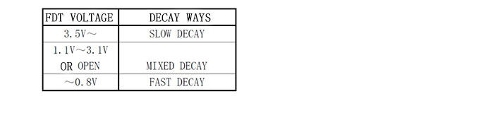
Package Included:
- 1 x Stepper Motor Driver Board