| Quantity | 3+ units | 10+ units | 30+ units | 50+ units | More |
|---|---|---|---|---|---|
| Price /Unit | $10.42 | $10.20 | $9.89 | $9.46 | Contact US |
 H2MD DC24-120V 6A Engraving Machine CNC Stepper Motor Driver Module Support Phase Dislocation Protection
$45.54
H2MD DC24-120V 6A Engraving Machine CNC Stepper Motor Driver Module Support Phase Dislocation Protection
$45.54
 ZM-3H2080 24V High Performance 3-Phase Stepper Motor Driver Controller AC80-220V for 86-130MM Stepper Motors
$166.32
ZM-3H2080 24V High Performance 3-Phase Stepper Motor Driver Controller AC80-220V for 86-130MM Stepper Motors
$166.32
 ZM-3H2080 12V High Performance 3-Phase Stepper Motor Driver Controller AC80-220V for 86-130MM Stepper Motors
$166.32
ZM-3H2080 12V High Performance 3-Phase Stepper Motor Driver Controller AC80-220V for 86-130MM Stepper Motors
$166.32
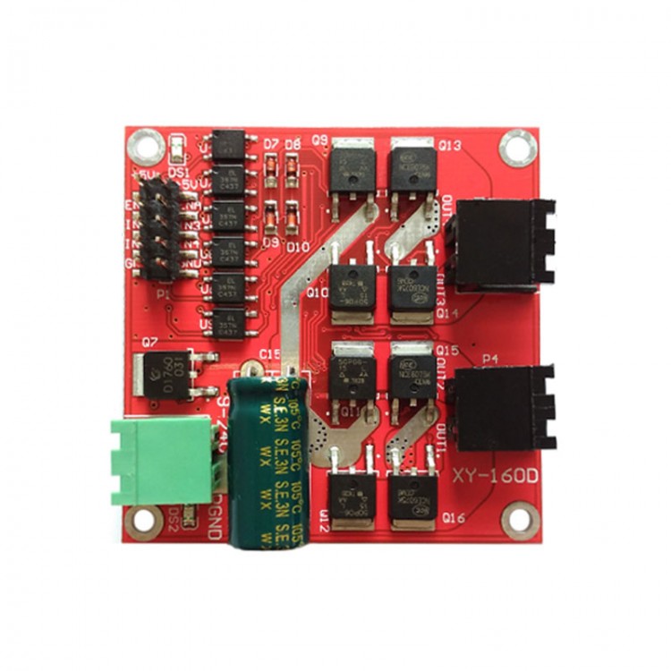
Industrial-Grade 2-Channel DC Motor Driver Module 7A 160W CW CCW PWM Speed Control L298 Logic XY-160D
Description:
Double H bridge driver module can drive two DC motors at the same time, one-channel 7A high power. It supports wide voltage 6.5V to 27V. Optocoupler isolated input signal. It is designed with isolation and under-voltage protection. It complies with EMC design specifications, has a static discharge circuit, which is stable and reliable.
Features:
- Dual H-bridge. Can drive two DC motors at the same time. One-channel 7A current with high power
- Wide voltage input 6.5V to 27V
- Signal optocoupler isolated input, which can be directly controlled by IO port without interference
- Under-voltage protection to prevent the module from being damaged by instantaneous high current
- High-power TVS and electrostatic discharge circuit suppress transient interference pulses and static electricity, enhance EMC performance, product stability and reliability, industrial-grade design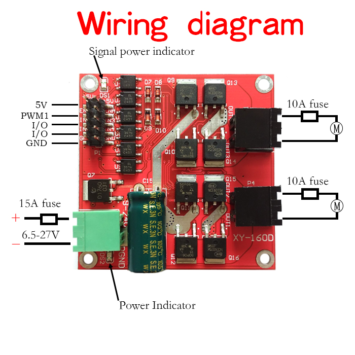
Control Signal Logic:
Note: 0 is low level, 1 is high level, x is any level, and it is high level when floating.
1.1 # motor interface control signal logic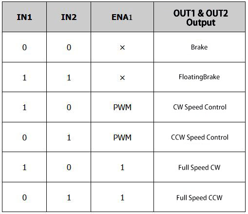
2.2 # motor interface control signal logic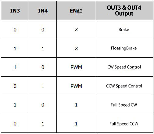
Specifications:
- Power supply voltage is 6.5V-27V. Power supply must not be reversedly connected or exceed 27V, otherwise the module may be burned out. It is recommended to connect a 15A fuse in series at the power input end.
- Two-way motor interface. Each channel has a rated output current of 7A and a peak current of 50A. The motor interface must not be short-circuited. It is recommended to connect a 10A fuse in series.
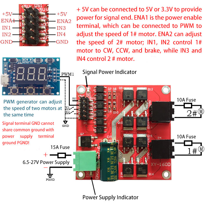
- Control signal voltage is 3-6.5V, which are enable signal, CW and CCW control signal separately.
- Enable signal terminal (ENA) inputs PWM adjustable speed, PWM frequency range 0-10KHZ, PWM minimum pulse width 10us.
- Working temperature: -25℃ to 80℃.
- Product size: 55 * 55 * 16mm (length, width, height).
- Installation hole diameter: 3mm. In order to prevent short circuit on the back when installing, you can add insulation pads or copper pillars to raise the circuit board.
Compatible Motor Parameters:
Suitable for motors with a rated voltage of 24V, marked with a rated power of 115W and below, or marked with a rated current of below 7A for a long time at full capacity.
Suitable for motors with a rated voltage of 12V, marked with a rated power of 40W or below, or marked with a rated current of below 7A for a long time at full capacity.
Precautions:
- Driver power supply does not allow reverse connection. It is recommended that a 15A fuse be connected in series at the power interface. Voltage should be between 6.5 to 27V. If the voltage is over-voltage, the drive module may be burned after power-on.
- It is recommended that the rated output current of power supply is more than 2 times of the rated current of your motor, so as not to make power supply failed to provide the required current when motor starts. When power supply voltage does not reach the input voltage required by the driver, the drive module performs under-voltage protection to turn off the output, causing the motor to stall.
- Motor interface must not be short-circuited, otherwise the drive module may be burned. It is recommended to connect a 10A fuse in series at the motor interface.
- When switching between CW and CCW, it is necessary to brake more than 0.1S before CCW. Do not change the direction before your motor stops, otherwise the driver may be damaged.
- When the drive module is powered off, do not rotate the motor directly or indirectly at high speed, otherwise the electromotive force generated by the motor may burn the drive module. If application needs to rotate the motor at high speed when the drive module is powered off, it is recommended to connect a relay in series with the motor interface of the drive (NO and COM terminals are connected in series), and the relay coil and the driver share the power. In this way, when the power fails, the relay will disconnect the driver from the motor.
- Be careful. Not to get the driver wet, or short circuit the components on the driver board, and not touch the pins and pads of the components on the board with your hand.
- Please read the above descriptions carefully before application.
Package Included:
- 1 x DC Motor Driver Module
Note: Please note that items are designed with wiring terminals by default. The pictures are displayed without inserted terminals.


 PLUS Ackerman Robot Car (Top-End Version w/ Independent Suspension Raspberry Pi 5 + N10P)")
