| Quantity | 3+ units | 10+ units | 30+ units | 50+ units | More |
|---|---|---|---|---|---|
| Price /Unit | $19.75 | $19.34 | $18.74 | $17.93 | Contact US |
AQMH2407ND Dual DC Motor Driver Module 12/24V 7A 160W DC Motor Driver Board H Bridge L298 Logic
Description:
This is an entry-level product for tanks, robots, laboratories, and DIY enthusiasts.
Features:
- Very small size 5.5x5.5cm/2.2x2.2"
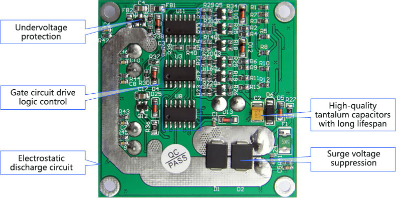
- Support voltage 7V~24V. With undervoltage protection and power supply transient interference suppression
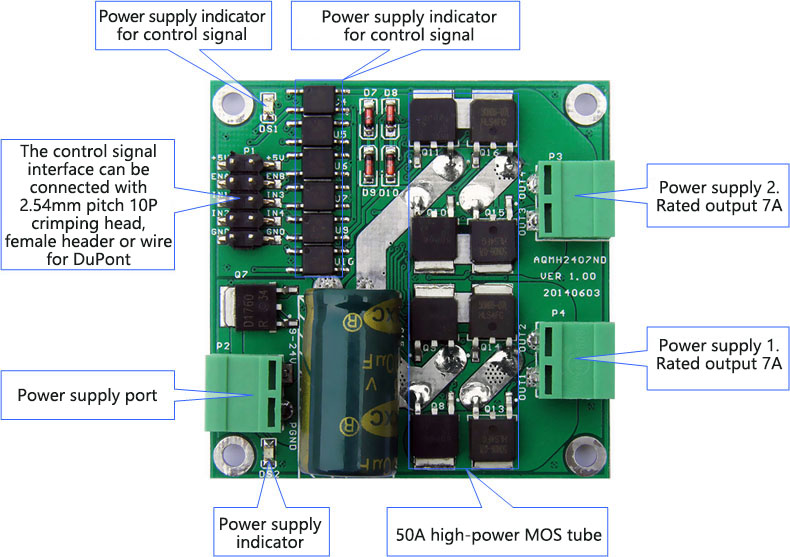
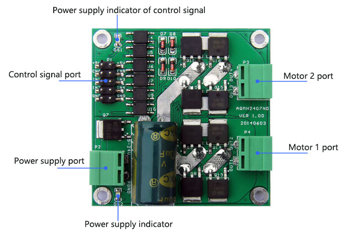
- Dual motor interface and rated output current 7A for each channel
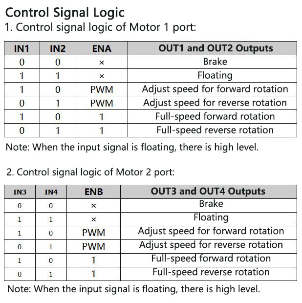
- Similar to L298 control logic, each channel supports three-wire control enable, forward and reverse rotation and braking
- Enable signal can be externally connected to PWM, and the positive and negative control signals can be connected in series with limit switches
- The control signal uses the sink current drive mode, which supports the direct drive of most MCU
- Use optocoupler to isolate all control signals
- An electrostatic discharge circuit
- Self-developed with intellectual property rights
Principle Overview:
This H-bridge module uses a gate circuit and a combination of MOS transistors to achieve motor forward and reverse, braking and speed regulation control. It has both larger output current and flexible control signal logic similar to L298.
Interference processing method: control signal optocoupler isolation, power supply spike voltage suppression.
Control signal logic: Use gate circuit to realize control logic similar to L298.
H-bridge realization method: P and N complementary MOS transistors are used to realize H-bridge.
Power supply undervoltage protection: Use reset chip to achieve undervoltage protection.
Technical Parameters:
- Power supply voltage range: DC 6.5V~27V
- Rated input voltage: DC 12V/24V
- Number of output channels: 2
- Rated output current per channel: 7A
- Peak current per channel: 50A
- Maximum adapted motor: 12V~40W; 24V~120W
- Control signal voltage range: 3~6.5V
- Control signal current per channel: 3~11mA
- Support PWM range: 0~100%
- Support PWM frequency range: 0~10kHz
- Working temperature: -25℃ to 80℃
- Dimensions: 5.5 x 5.5 x 1.4cm/2.2 x 2.2 x 0.6"
Package Included:
- 1 x DC Motor Driver Board
Parameters of Compatible Motors:
- Motor with rated voltage 24V: Suitable for motors with rated power of 115W and below or rated current below 7A to work at full capacity for a long time
- Motor with rated voltage of 12V: suitable for motors with rated power of 40W or less or rated current of below 7A to work at full capacity for a long time
Attention:
The driver can output a rated current of 7A for a long time. But the rated power on the motor generally refers to the output power. Considering the work loss of the motor, the motor efficiency should be considered when calculating the rated current. Rated current = rated power/rated voltage/efficiency.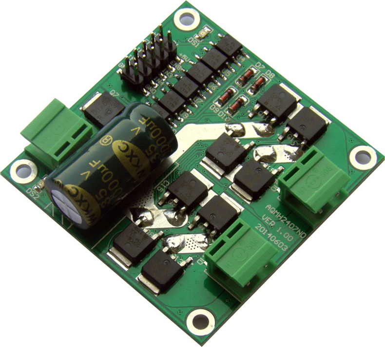
Typical Connection Examples:
1. Use MCU to Control the rotation of Motor: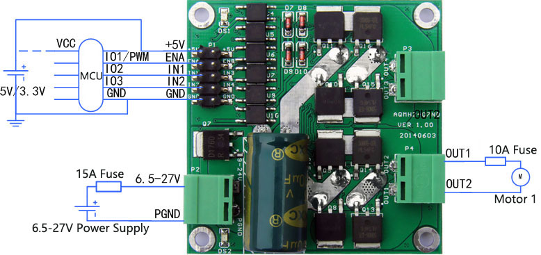
The MCU power supply and the driver board's control signal power supply should share the same ground, but not the same ground with the motor power supply PGND. When using a 5V MCU, the driver board +5V is connected to the power supply +5V. When using 3.3V MCU, the driver board +5V is connected to the power supply 3.3V. MCU and drive board control signals can share a power supply or independently supply power (but must share the same ground). ENA is connected to a GPIO or PWM output port of the MCU. When ENA is high, the drive board is enabled, forward and reverse or brake is effective. If it is a PWM signal, the motor can be adjusted; when it is low, drive The board is disabled, and the motor interface has no output. IN1 and IN2 are connected to the two GPIOs of MCU (supporting any IO port of 51 MCU, no pull-up resistor is needed), to control the forward and reverse rotation and braking of the motor, and the driver logic is shown in the table above.
2. Use buttons to Control the Forward and Reverse Rotation of Motor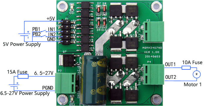
PB1 and PB2 are two buttons. When PB2 is pressed but PB1 is not pressed, IN1 is high level and IN2 is low level, and your motor rotates forward. When PB1 is pressed but PB2 is not pressed, IN1 is low level and IN2 is high level, and your motor reverses. When PB1 and PB2 are pressed down or both pop up, IN2 and IN2 are both low level or high level, and the motor brakes (or brake). See logic table for control signal logic.
The mounting hole diameter is 3mm/0.12". It is recommended to use M3 screws for fixing. Be careful not to short-circuit the back circuit during installation. You can add insulating pads or use copper pillars to raise the circuit board.
Precautions:
1) Please connect the power supply of the driver correctly. It is recommended to connect a 15A fuse in series with the power supply port, and the voltage should be between 6.5V and 27V. If it is overvoltage, the drive module may be burnt when powered on.
2) It is recommended that the rated output current of the power supply is more than 2 times the rated current of your motor, so as not to cause the power supply to fail to provide the current required when the motor starts. Or it will cause the power supply voltage to drop so that the power supply voltage cannot reach the input voltage required by the drive, so that the drive module performs undervoltage protection and shuts off the output, causing the motor to stall.
3) The motor interface cannot be short-circuited, otherwise the drive module may be burned. It is recommended to connect a 10A fuse in series with the motor interface.
5) The drive should be connected to motors before powering on to prevent short-circuit and burn the drive module.
6) The drive cannot not get wet. Not short-circuit the components on the driver board. Not touch the pins and pads of the components on the board with your hands.


