| Quantity | 3+ units | 10+ units | 30+ units | 50+ units | More |
|---|---|---|---|---|---|
| Price /Unit | $1,127.97 | $1,104.95 | $1,070.42 | $1,024.38 | Contact US |
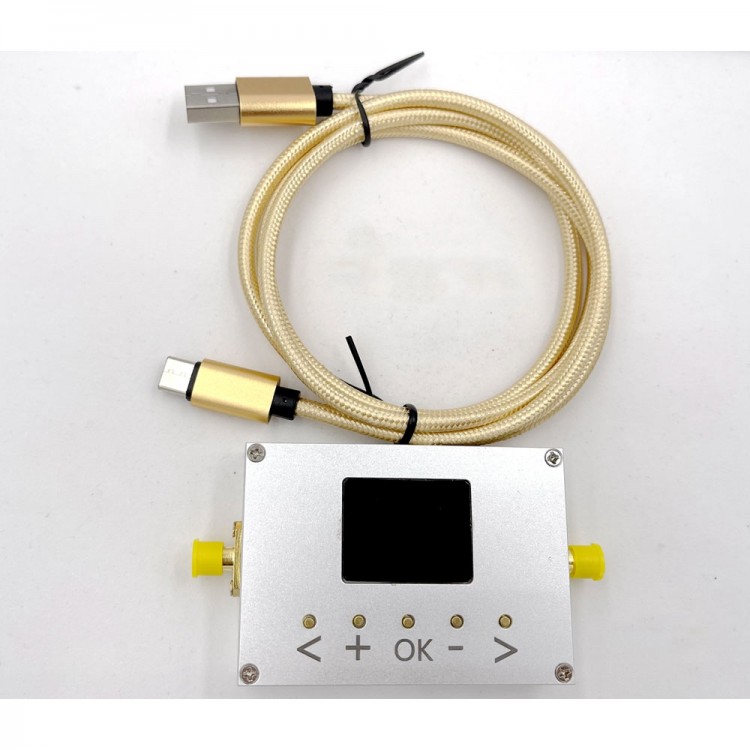
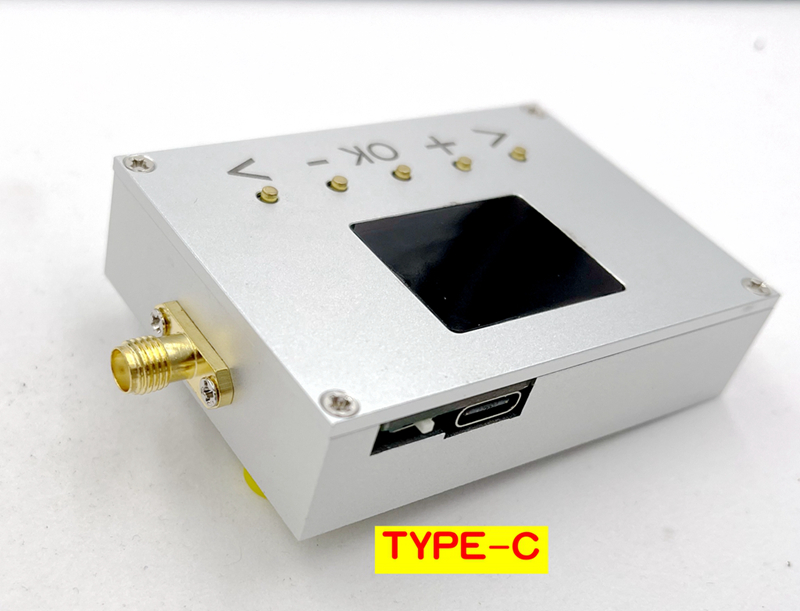
LMX2820 RF Signal Generator Signal Source 45MHz-22.6GHz PLL Local Oscillator Radar Continuous Wave
Specifications:
- Module size: 8*48*17mm
- Net weight: 100g
- PL2303 is connected to your computer and provides a communications protocol
Package Included:
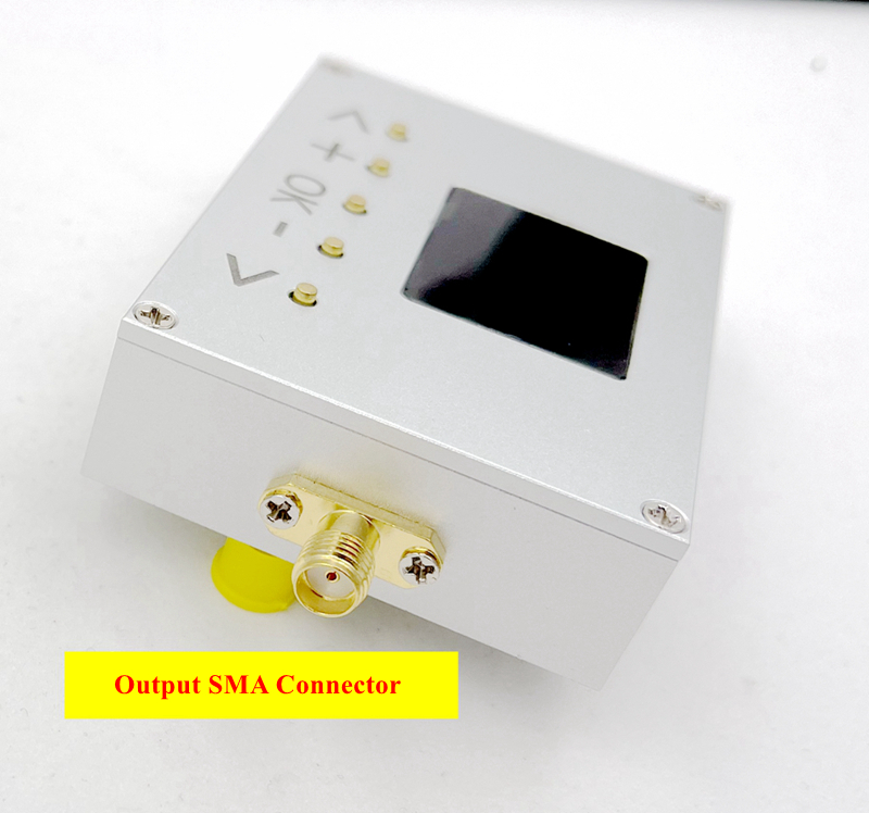
- 1 x RF Signal Generator Host
- 1 x Type-C Cable
LMX2820 Chip Characteristics: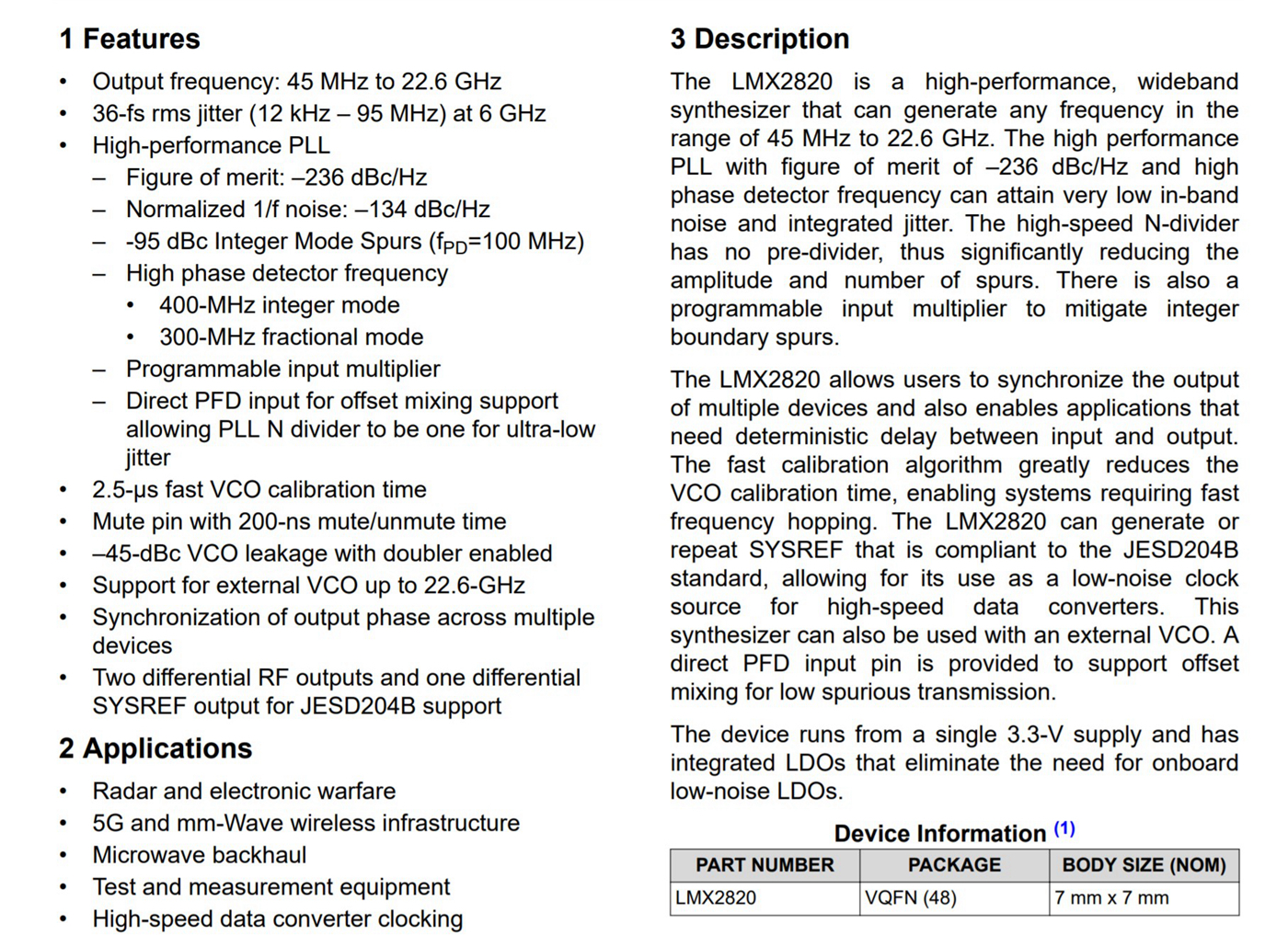
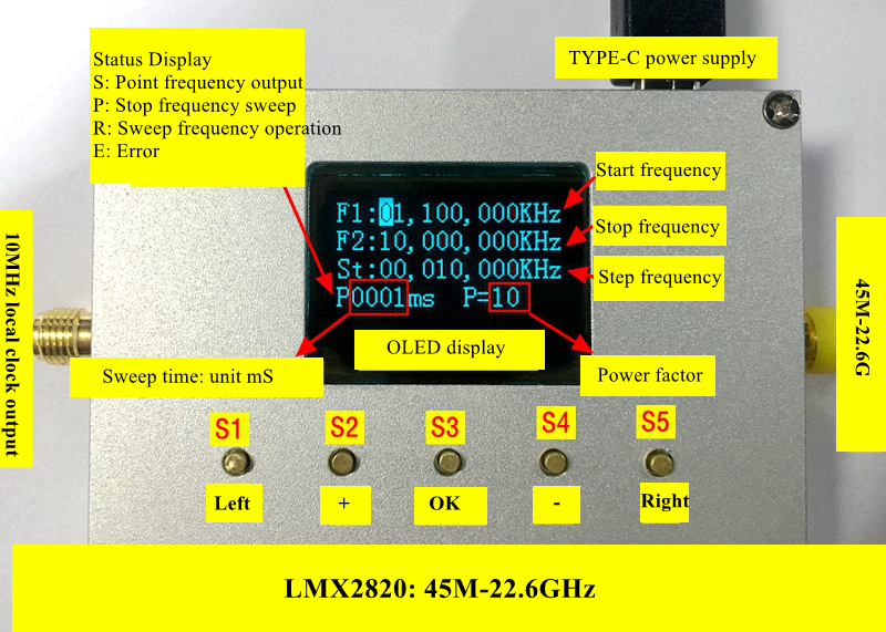

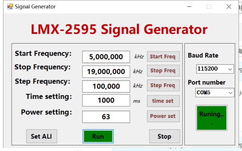
LMX2595-LMX2820 General Host Computer Operation:
RF Signal Source PC Communications Protocol:
The overall structure of PC protocol adopts command line mode, and the communication baud rate is 115200bps. A PC sends out the command, the local machine parses and executes it, and then returns the result to the PC. Commands are limited to lowercase letters a~z, numbers 0~9, and the end of each command is the # symbol (0x23 in hexadecimal), and the maximum length of the PC command is 15 characters (including #).
1. W Command (the host computer sends data to the main control board)
1.1 WC Command: set frequency value, start frequency, stop frequency, step frequency.
- The format is: wcxx xxx xxx#, a total of 11 bytes. Where "c" is a different frequency value.
- w1: write start frequency
- w2: write termination frequency
- w3: write step frequency
- Where xx xxx xxx is the frequency value represented by 8 digits, such as: 01 000 000 means that the set frequency is 01 000 000KHz (1GHz)
1.2 Start Command: The main control board starts data scanning and transmits data to the host computer in real time. The format is: start#, a total of 6 bytes.
1.3 Stop Command: Stop scanning. The format is: stop#, a total of 5 bytes.
1.4 WP Command: amplitude value command. The format is: wpxxxx #, a total of 7 bytes. Where xxxx is the amplitude factor represented by 4 ASIIs (only the last 2 digits are used), there is no need to convert the dbm value, and there is no decimal point, only the value needs to be sent. The range is 00-63 (no unit, just an amplitude factor)
- wp0001, the lower computer displays P=02
- wp0010, the lower computer displays P=10
1.5 Ti Command: Scan time command (maximum 9999)
- The format is: tixxxx #, a total of 7 bytes; where xxxx is the amplitude value represented by 4 ASII numbers, for example: 0001 means that the sweep time is set to 1mS (the fastest sweep time, the time to step one frequency point)
- 0010 means that the scan time is set to 10mS
- 1000 means that the scan time is set to 1S
- 0022 means that the scan time is set to 22mS
2. The host sends data to the host computer (response value):
- After receiving the correct data, it returns OK$