| Quantity | 3+ units | 10+ units | 30+ units | 50+ units | More |
|---|---|---|---|---|---|
| Price /Unit | $30.71 | $30.09 | $29.15 | $27.89 | Contact US |
 G1009 10-inch Embedded HD Industrial Monitor 1024x768 Hook Mount TFT Display with BNC/VGA/AV/HDMI-compatible Ports
$109.57
G1009 10-inch Embedded HD Industrial Monitor 1024x768 Hook Mount TFT Display with BNC/VGA/AV/HDMI-compatible Ports
$109.57
 G121SN01 V3 Color Active Matrix LCD Display Panel Designed for Various Industrial Applications
$88.42
G121SN01 V3 Color Active Matrix LCD Display Panel Designed for Various Industrial Applications
$88.42
 RTU-307D NET-07D 8AI-8DI-8DO Data Acquisition Module IO Module (RS485+RS232) for Industrial Use
$76.89
RTU-307D NET-07D 8AI-8DI-8DO Data Acquisition Module IO Module (RS485+RS232) for Industrial Use
$76.89
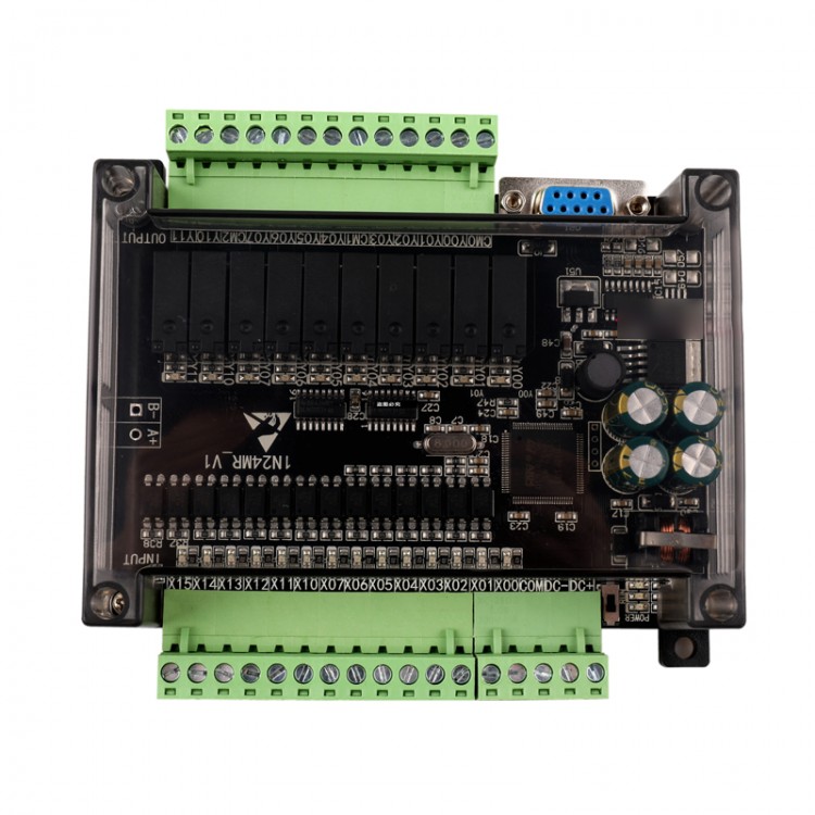
Note:
1. The board is powered by DC 24V. Do not input AC or 220V.
2. The board uses the serial port to download the program. If the computer does not have a serial port, please purchase the USB to serial cable.
Description:
1. Write application in ladder language, support GX-Develoer, GX-WORK2
2. Support human-machine interface connection, the application is similar as FX1N.
3. Support ladder programming, download, monitor.
4. The programming port is the port for downloading and communicating with the man-machine interface.
5. This PLC adopts industrial-grade 32-bit MCU with strong anti-interference, and its running speed far exceeds the original FX1N.
6. The company's original password protection, as long as the password is 12345678 internal programs are protected, to prevent your program from being illegally stolen, to protect your labor results. If the password is set to 12345678 and there is no program reading function, you can only download the program and the "parameter" option cannot be checked when downloading. Unable to unlock password! !
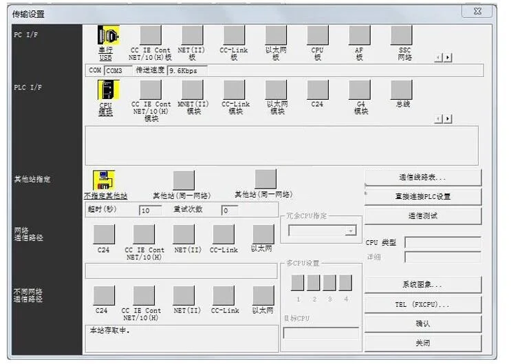
This PLC transmission baud rate is 9600 as shown below

|
project |
performance |
|
|
Operation control method |
Stored program repeatedly scanning mode |
|
|
Input and output control mode |
Batch mode (when executing END instruction), input and output refresh command, pulse capture function |
|
|
Programming language |
Ladder diagram, SFC stepping instructions |
|
|
Ladder programming software |
GX Developer, GX Works2 |
|
|
Program memory |
8K step EEPROM |
|
|
Type of instruction |
Direct instruction |
27 |
|
Step ladder instruction |
2 |
|
|
Basic application instruction |
70 |
|
|
Instructions speed |
Basic instructions |
0.1μS-0.55μS instruction |
|
Application instructions |
0.8μS-10μS instruction |
|
|
input Output |
Input relay X |
X0-X127,128 points |
|
Output relay Y |
Y0-Y127,128 poinst |
|
|
Auxiliary relay M |
General use |
M0-M1523,1524 points |
|
Special use |
M8000-M1535,1152 points( after M500 Power down save) |
|
|
State S |
S10-S999,1000 points |
|
|
Timer T |
100MS |
T0-199,200 points |
|
10MS |
T200-T245,46 points |
|
|
1MS |
T246-T249,4 points |
|
|
100MS accumulation |
T250-T255,6 points |
|
|
Counter C |
Counter 16 bits |
C0-C199,200point(after C100 Power down save) |
|
Counter 32 bits |
C200-C255,56 points |
|
|
Data register |
General use |
D0-D500(after D200 Power down save),500point |
|
Special use |
D8000-D8255,255 points |
|
|
Indexing |
V7-V0,Z7-Z0,16 points |
|
|
Nested pointer |
P0-P127,128 points |
|
|
constant |
K 16 bit |
-32768-32767 |
|
K 32 bit |
-2 147 483 648-2 147 483 647 |
|
|
H 16 bit |
0-FFFF |
|
|
H 32 bit |
0-FFFFFFFF |
|
27 basic instructions
|
Mnemonic, name |
function |
Available Soft Components |
|
[LD] take |
Operation start“a”contact |
XYMSTC |
|
[LD] take reverse |
Operation start“b”contact |
XYMSTC |
|
[LDP] take pulse rising edge |
The rising edge detects the start of the operation |
XYMSTC |
|
[LDF] take the pulse falling edge |
The falling edge detects the start of the operation |
XYMSTC |
|
[AND] and |
Series“a”contact |
XYMSTC |
|
[ANI] and reversal |
Series“b”contact |
XYMSTC |
|
[ANDP] with pulse rising edge |
The rising edge detects“a”series connection |
XYMSTC |
|
[ANDF] with pulse falling edge |
Falling edge detects serial connection |
XYMSTC |
|
[OR] or |
Parallel“a”contact |
XYMSTC |
|
[ORI] or inversion |
Parallel“b”contact |
XYMSTC |
|
[ORP] or pulse rising edge |
The rising edge detects a parallel connection |
XYMSTC |
|
[OUT]output |
Coil drive command |
YMSTC |
|
[SET] set |
Coil hold command |
YMS |
|
[RST]Reset |
Coil reset command |
YMSTCD |
|
[PLS] rising edge pulse |
Rising edge detection command |
YM |
|
[PLF] rising edge pulse |
Falling edge detection instruction |
YM |
|
[MC] Master |
Connecting coil of common series point |
|
|
[MCR] master reset |
Clearing coil of common series point |
|
|
[MPS] onto the stack |
Operational storage |
|
|
[MRD] read stack |
Storage readout |
|
|
[MPP] popping |
Save read and reset
|
|
|
[INV]Reverse |
Reverse of operation result |
|
|
[NOP] empty operation |
No action |
|
|
[END] end |
End of sequence program |
|
Two step ladder diagram instructions
|
STL step ladder |
Step ladder start |
|
|
RET return |
Step ladder end |
|
Application instruction
|
classification |
FNC NO. |
Instruction mnemonic |
Instruction name |
|
Procedure flow chart |
00 |
CJ |
Conditional jump |
|
01 |
CALL |
Subroutine call |
|
|
02 |
SRET |
Subroutine return |
|
|
06 |
FEND |
End of main program |
|
|
07 |
WDT |
Watchdog timer |
|
|
08 |
FOR |
Repeat range begins |
|
|
09 |
NEXT |
End of repeat range |
|
|
Transfer and comparison |
10 |
CMP |
Comparison |
|
11 |
ZCP |
Regional comparison |
|
|
12 |
MOV |
Transfer |
|
|
15 |
BMOV |
Batch transfer |
|
|
18 |
BCD |
BCD exchange |
|
|
19 |
BIN |
BIN exchange |
|
|
Four arithmetic operations |
20 |
ADD |
BIN addition |
|
21 |
SUB |
BIN subtraction |
|
|
22 |
MUL |
BIN multiplication |
|
|
23 |
DIV |
BIN division |
|
|
24 |
INC |
BIN increment |
|
|
25 |
DEC |
BIN decrement |
|
|
26 |
WAND |
Logic and |
|
|
27 |
WOR |
Logical or |
|
|
28 |
WXOR |
Logical XOR |
|
|
Rotation displacement |
34 |
SFTR |
Right shift |
|
35 |
SFTL |
Left shift |
|
|
38 |
SFWR |
Shift write |
|
|
39 |
SFRD |
Shift write out |
|
|
Bit processing |
40 |
ZRST |
Reset all |
|
41 |
DECO |
decoding |
|
|
42 |
ENCO |
coding |
|
classification |
FNC NO. |
Instruction mnemonic |
Instruction name |
|
High speed processing |
56 |
SPD |
Pulse density |
|
57 |
PLSY |
Pulse output |
|
|
59 |
PLSR |
Adjustable speed pulse output |
|
|
Easy command |
66 |
ALT |
Alternate output |
|
67 |
RAMP |
Ramp signal |
|
|
Positioning |
156 |
ZRN |
Origin return |
|
157 |
PLSV |
Variable pulse output |
|
|
158 |
DRVI |
Corresponding position control |
|
|
159 |
DRVA |
Absolute position control |
|
|
Contact comparison instruction |
224 |
LD= |
Start of operation (S1) = (S2) turn on |
|
225 |
LD﹥ |
Start of operation (S1) ﹥(S2) turn on |
|
|
226 |
LD﹤ |
Start of operation (S1) ﹥(S2) turn on |
|
|
228 |
LD﹤﹥ |
Start of operation (S1) ≠(S2) turn on |
|
|
229 |
LD﹤= |
Start of operation (S1) ≤(S2) turn on |
|
|
230 |
LD﹥= |
Start of operation (S1) ≥(S2) turn on |
|
|
232 |
AND = |
Series connection (S1) = (S2) conduction |
|
|
233 |
AND﹥ |
Series connection (S1) ﹥(S2) conduction |
|
|
234 |
AND﹤ |
Series connection (S1) ﹥(S2) conduction |
|
|
Contact comparison instruction |
236 |
AND﹤> |
Series connection (S1) ≠(S2) conduction |
|
237 |
AND﹤= |
Series connection (S1) ≤(S2) conduction |
|
|
238 |
AND>= |
Series connection (S1) ≥(S2) conduction |
|
|
240 |
OR = |
Parallel connection (S1) = (S2) conduction |
|
|
241 |
OR﹥ |
Parallel connection (S1) ﹥(S2) conduction |
|
|
242 |
OR﹤ |
Parallel connection (S1) ﹥(S2) conduction |
|
|
243 |
OR﹤﹥ |
Parallel connection (S1) ≠(S2) conduction |