| Quantity | 3+ units | 10+ units | 30+ units | 50+ units | More |
|---|---|---|---|---|---|
| Price /Unit | $50.70 | $49.66 | $48.11 | $46.04 | Contact US |
 WHEELTEC H30 MINI High Precision 9-Axis IMU Inertial Navigation Module Type-C/SH1.0 6Pin Output Support for ROS1/ROS2
$61.62
WHEELTEC H30 MINI High Precision 9-Axis IMU Inertial Navigation Module Type-C/SH1.0 6Pin Output Support for ROS1/ROS2
$61.62
 LC29HBS Dual Band Multi-constellation Base Station GNSS Module + Antenna with RTK Function GPS/BDS/Galileo/QZSS/GLONASS
$45.10
LC29HBS Dual Band Multi-constellation Base Station GNSS Module + Antenna with RTK Function GPS/BDS/Galileo/QZSS/GLONASS
$45.10
 LC29HBS Dual Band Multi-constellation Base Station GNSS Module with RTK Function GPS/BDS/Galileo/QZSS/GLONASS
$33.44
LC29HBS Dual Band Multi-constellation Base Station GNSS Module with RTK Function GPS/BDS/Galileo/QZSS/GLONASS
$33.44
UWB Module Indoor Positioning Precise Close-Range Distance Measurement NodeMCU-BU01 Development Board
Functional Features:
Based on DW1000 chip development, the module integrates antenna, all radio frequency circuits, power management and clock modules. The module can use two-way ranging or TDOA positioning system with a positioning accuracy of 10cm and a data transmission rate of up to 6.8Mbps. It is widely used in nursing homes, parking lots, etc.
UWB Positioning Technology Advantages:
UWB positioning technology has significant advantages such as large system capacity, fast transmission speed, low transmission power, high multipath resolution, good system confidentiality, high positioning accuracy, and strong penetration capability. (Attention: The positioning index of Bluetooth technology refers to the current mainstream version, and does not refer to the Bluetooth 5.1 version.)
Product Parameters:
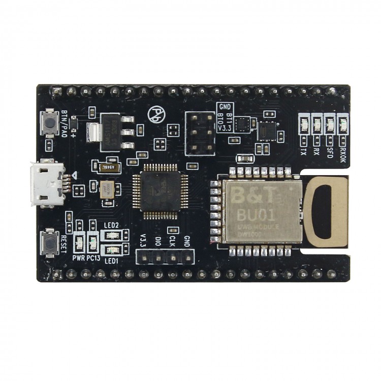
- Module Model: NodeMCU-BU01
- Package form: DIP-40
- Module size: 35*55.5(±0.2) mm (W*H)
- Protocol standard: EEE 802.15.4-2011 UWB
- Support interface: PWM/I2C/GPIO, all IO of MCU
- Spectrum range: 3.5~6.8GHz
- Antenna form: onboard PCB antenna, transmission distance is about 40 meters
- Transmit power: 802.11b: 16±2dBm; 802.11g: 16±2dBm; 802.11n: 16±2dBm;
- Power supply range: 5V/3.3V
- Working temperature: industrial grade -40C to +85℃
Package Included:
- 1 x UWB Module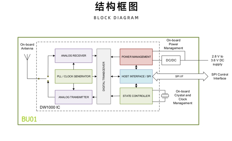

Pin Introduction:
- Pin 1: I07. Function: The default value is used as SYNC input. This pin can be reconfigured as general I/O pin GPI07 under software control.
- Pin 2: I06. Function: General I/O pin. At power-up, it is used as the SPIPHA (SPI phase selection) pin for configuring the SPI operating mode. After power-on, this pin will default to a general-purpose I/O pin.
- Pin 3: I05. Function: General I/O pin. At power-up, it is used as the SPIPOL (SPI Polarity Selection) pin for configuring the SPI operating mode. After power-on, this pin will default to a general-purpose I/O pin.
- Pin 4: I04. Function: General I/O pin.
- Pin 5: IRQ. Function: Interrupt request output from DWM1000 to host processor, and connect to PB0 of MCU. By default, IRQ is an active high output, but if necessary, IRQ can be configured to be active low. In order to operate correctly in SLEEP and DEEPSLEEP modes, it should be configured for active high operation. This pin will float in sleep and DEEPSLEEP states. Unless it is pulled low, it may cause a false interrupt. When the IRQ function is not used, this pin can be reconfigured as the general-purpose I/O line GPI08.
- Pin 6: CLK. Function: SPI clock and connect to PA5 of MCU.
- Pin 7: MISO. Function: SPI data output and connect with PA6 of MCU.
- Pin 8: MOSI. Function: SPI data input and connect with PA7 of MCU.
- Pin 9: CSN. Function: SPI chip selection and connect with PA4 of MCU. This is an active low enable input. A high-to-low transition on SPICSn means that a new SPI transaction begins. SPICSn can also be used as a wake-up signal to make DW1000 go out of sleep or sleep state.
- Pin 10: PA3. Function: PA3 on the MCU.
- Pin 11: PB1. Function: PB1 on the MCU.
- Pin 12: PB10. Function: PB10 on the MCU.
- Pin 13: PB11. Function: PB11 on the MCU.
- Pin 14: LED1. Function: PA2 on the MCU, connect to LED1
- Pin 15: LED2. Function: PA1 on MCU, connect to LED2
- Pin 16: BTN. Function: PA0 on MCU, connect to BTN button
- Pin 17: RESET. Function: Reset pin on MCU, connected to reset button
- Pin 18: GND. Function: Ground
- Pin 19: GND. Function: Ground
- Pin 20: V3.3. Function: 3.3V power supply
- Pin 21: V5. Function: 5V power supply
- Pin 22: V3.3. Function: 3.3V power supply
- Pin 23: GND. Function: Ground
- Pin 24: VBAT. Function: MCU battery power supply Vbat (battery is not included)
- Pin 25: SCL. Function: The SCL pin on the MCU is pulled up to 3.3V by default, and the sensor SCL pin is connected internally
- Pin 26: SDA. Function: The SDA pin on the MCU is pulled up by 3.3V by default, and the SDA pin of the sensor is internally connected
- Pin 27: PB8. Function: PB8 on the MCU
- Pin 28: PB9. Function: PB9 on the MCU
- Pin 29: PB5. Function: PB5 on the MCU
- Pin 30: PB4. Function: PB4 on the MCU
- Pin 31: PB3. Function: PB3 on the MCU
- Pin 32: PA15. Function: PA15 on the MCU
- Pin 33: V3.3. Function: 3.3V power supply
- Pin 34: RST. Function: Reset pin on BU01 and connect to PB 12 of MCU
- Pin 35: WAKEUP. Function: The wake-up pin on BU01 is connected to the PB13 of the MCU. When set to an active high state, the WAKEUP pin brings the DW1000 from sleep or DEEPSLEEP state into working mode. If not used, this pin can be grounded
- Pin 36: EXTON. Function: The EXTON pin on BU01 is connected to PB14 of MCU, and the external device is enabled. Set during wake-up and remain active until the device enters sleep mode. Can be used to control external DC-DC converters or other circuits that are not needed when the device is in sleep mode to minimize power consumption
- Pin 37: U1RX. Function: UART1-RX on the MCU
- Pin 38: U1TX. Function: UART1-TX on the MCU
- Pin 39: PA8. Function: PA8 on the MCU
- Pin 40: PB15. Function: PB15 on the MCU
- Pin DI0: Swdio. Function: SWDIO pin on the MCU. Default MCU burning pin.
- Pin CLK: Swclk. Function: SWDIO pin on the MCU. Default MCU burning pin.
- Pin BT0: BOOT0. Function: BOOT0 pin on the MCU, control start way of MCU
- Pin BT1: BOOT1. Function: BOOT1 pin on the MCU, control start way of MCU
- RESET Button: RESET. Function: Reset.
- BTN/PA0 Button: BTN/PA0. Press the button to raise the PA0 pin.


")
")

 PLUS Ackerman Robot Car Top-End Version w/ Independent Suspension Orin NX 8GB + C16 Lidar")


 PLUS Ackerman Robot Car High-End Version w/ Swing Suspension Raspberry Pi 5 8GB + N10P")