| Quantity | 3+ units | 10+ units | 30+ units | 50+ units | More |
|---|---|---|---|---|---|
| Price /Unit | $7.75 | $7.59 | $7.36 | $7.04 | Contact US |
 AD2S1210 N1 16Bit R/DC High Performance Resolver Transformer Demodulation Module 15.8Vpp Excitation Amplitude
$77.75
AD2S1210 N1 16Bit R/DC High Performance Resolver Transformer Demodulation Module 15.8Vpp Excitation Amplitude
$77.75
 GC-1201S Two-master One-slave Isolated RS485 Hub Repeater Double Electrical Isolation with 12V Power Supply
$36.58
GC-1201S Two-master One-slave Isolated RS485 Hub Repeater Double Electrical Isolation with 12V Power Supply
$36.58
 GC-1201S Two-master One-slave Isolated RS485 Hub Repeater Double Electrical Isolation Support for Modbus Protocol
$33.75
GC-1201S Two-master One-slave Isolated RS485 Hub Repeater Double Electrical Isolation Support for Modbus Protocol
$33.75
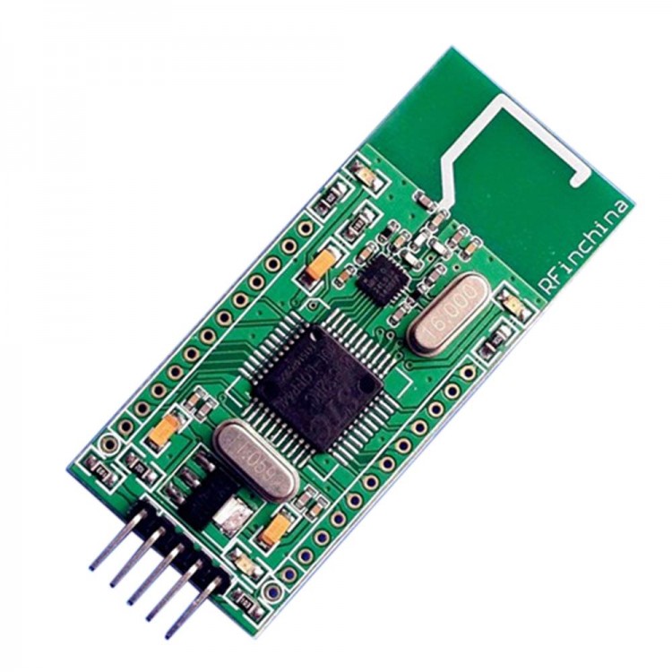
Wireless Module Programmable Define Function Board Integrated STC89C52 NRF24L01+ for DIY
Hardware parameters:
- MCU models: ST89C52 series (ROM: 8 k, RAM: 512, crystals: 11.0592 MHZ)
- Wireless models: NRF24L01 + (NRF24L01 upgrade version)
- Basic function: 2.4 GHZ wireless dual-way communication function test (provide test function source program)
- Pin function: IO all extensions (except NRF24L01 + takes 6 IO)
- Download: the ISP serial program (can select professional USB download line)
- TXD RXD is general TTL level a serial port
- Both sides of the module, a total of 24 IO (P0 - P2 and P3) can be used directly,
- You can connect the sensor, section key, you can extend the LCD LED and so on
- Reserved 5 pins for program download and seriel communication
Software function:
Module has the following functions, users can test according to the following effect:
Functional test 1: wireless communication between single-chip microcomputer and single chip microcomputer
Basic function:dual-way remote communication
Application: can be used with wireless remote control, wireless control
Steps:
1. When P2.0 (KEY1) with the round hole (GND) the side of its sub with forceps, namely the MCU detects P2.0 for low level, send data then LED1 lights,corresponding to the other side receiving the data, if the data is correct, the LED indicator light flashing.
2. When P3.7 (KEY2) with the round hole (GND) the side of its sub with forceps, namely the MCU detect P3.7 for low level, send data to the machine module LED2 light is lit, corresponding to the other side receiving the data, if the data is correct, the LED indicator light flashing.
Remark:
If either part through the USB to TTL module and PC connection, open the serial port assistant software, if in accordance with the above operation, in addition to the above LED change effect, a serial port assistant software can display the data received, specific as follows:
When P2.0 (KEY1) with the round hole (GND) the side of its sub with forceps, namely the MCU detect P2.0 for low level, send data, the other side of the corresponding after receiving the data, if the data is correct, the LED indicator lights flashing.At the same time, the receiver serial assistant software area
Displays the following effects:
20 00 00 00 00 00 00 00 00 00 00 00 00 00 00 0000 00 00 00 00 00 00 00 00 00 00 00 00 00 00 00
Remark: 32 bytes, 32 bytes of data, of course, this can be freely defined, transceiver 32 bytes at a time
When P3.7 (KEY2) with the round hole (GND) the side of its sub with forceps, namely the MCU detect P2.0 for low electricity at ordinary times, send data, the other side of the corresponding after receiving the data, if the data is correct, the LED indicator lights flashing.At the same time, the receiver serial assistant software area
Displays the following effects:
37 00 00 00 00 00 00 00 00 00 00 00 00 00 00 0000 00 00 00 00 00 00 00 00 00 00 00 00 00 00 00
Remark: 32 bytes, 32 bytes of data, of course, this can be freely defined, transceiver 32 bytes at a time
Functional test 2: UART equipment (computer) and wireless communication between UART equipment (computer)
Basic function: the bidirectional serial port
Application: application and UART interface equipment, wireless transmission and transmission between the computer and the computer
Steps:
1: install USB to TTL module driver (PL2303HX drive provided free of charge)
2: USB to TTL module and 24 l01 JASK51 - good respectively connected with two computer USB interface (also can use a computer two USB interface test)
3: open the serial debugging assistant software respectively, and choose a serial port number, baud rate defaults to 9600 (when a computer test, two virtual serial port)
4: when any one party sent serial port assistant software after 32 bytes of data, the sending module of LED1 LDE2 are flashing, but after you receive the corresponding receiving module
LED1 LDE2 flashing, also receive complete, at the same time, the assistant software serial port receiving area will display the received data.
If one party sends the following 32 bytes of data data (optional)
01, 02, 03 04 05 06 07, 08 09 10 11 12 13 14 15 16
17 18 19 20, 21, 22, 23 24 25, 26 and 27, 28 and 30, 31 and 32
32 bytes of data, the other party will also receive data (optional)
01, 02, 03 04 05 06 07, 08 09 10 11 12 13 14 15 16
17 18 19 20, 21, 22, 23 24 25, 26 and 27, 28 and 30, 31 and 32
NRF24L01 / NRF24L01 + is Norway NordicVLSI company released a new rf transceiver devices, using 4 mm x 4 mmQFN20 encapsulation;NRF24L01 / NRF24L01 + work in ISM frequency band: 2.4 ~ 2.524 GHz.And built-in frequency synthesizer, power amplifier, crystal oscillator, modulator and enhanced ShockBurst technology and fusion, including address, output power and communication channel can be configured by the program, suitable for use in a multimachine communication.NRF24L01 / NRF24L01 + power consumption is low, in - 6 dBm power launch, working current is only 9 mA;And the corresponding receiver working current 12.3 mA, a variety of low power mode (power lost mode and idle mode) envoys to design more convenient.NRF24L01 / NRF24L01 + in the industry-leading features make it particularly suitable for low power consumption using 2.4 G application of button batteries, the entire solution including the link layer and MultiCeiver function provides nRF24XX more than the existing function and lower power consumption, compared with the current bluetooth technology in the provision of a higher rate, and it only takes less power consumption. The latest NRF24L01 + compatible with NRF24L01, and an increase of 250 KBPS low speed function.
NRF24L01 / NRF24L01 + basic features:
- Operating voltage: 1.9-3.6 V
- Modulation mode: GFSK
- Maximum transmitted power: 0 DBM
- The maximum transmission rate: 2 MBPS
- Maximum working current moment: &; 15 ma
- Working frequency (2.400 to 2.524 GHZ)
- 1.9 3.6 V low voltage work
- Power down mode power consumption of 400 na
- The power consumption of 32 ua standby mode
- 130 us quickly switch and wake time
- A piece of stabilizer in oltage regulators
- 2 Mbit/s rate when receiving the current of 12.5 mA
- 2 Mbit/s @ 0 DBM output rate when the current of 11 ma
- MultiCeiverMT hardware provides the function of the six receiver at the same time, 2 mbit/s that makes it possible to high-quality VoIP industry leading low-power NRF24L01 / NRF24L01 + is especially suitable for using 2.4 G application of button batteries, the entire solution including the link layer and MultiCeiver function provides nRF24XX more than the existing function and lower power consumption, compared with the current bluetooth technology
A- t the same time of providing higher rate, and it only takes a smaller power consumption
- Open communication about 60 meters distance, indoor 30 meters
Software instructions video: click here
Program download video: click here
Package included:
- 1 x Wireless Module
- 1 x Battery box
- 2 x Pin