| Quantity | 3+ units | 10+ units | 30+ units | 50+ units | More |
|---|---|---|---|---|---|
| Price /Unit | $40.71 | $39.88 | $38.63 | $36.97 | Contact US |
 SUP-C703S Signal Generator & Process Calibrator – mA, V, Ω, RTD, Thermocouple Output & Measurement
$156.44
SUP-C703S Signal Generator & Process Calibrator – mA, V, Ω, RTD, Thermocouple Output & Measurement
$156.44
 6000A 20µH Air Core Inductor for Dual Pulse Testing and High-Performance Electrical Experiments
$86.76
6000A 20µH Air Core Inductor for Dual Pulse Testing and High-Performance Electrical Experiments
$86.76
 DP8000 Max IGBT Pulse Generator with Internally Integrated IGBT Driver (Air Core Inductor Included)
$384.16
DP8000 Max IGBT Pulse Generator with Internally Integrated IGBT Driver (Air Core Inductor Included)
$384.16
HW-210K Dual-Channel VI Curve Tester Circuit Board Tester Online Detection w/ Four Test Frequencies
Description:
This handheld VI curve tester has 4 test frequencies. The portable tester can be used when connected to an oscilloscope. Both analogs oscilloscopes and digital oscilloscopes can be used. If you are looking for a circuit board tester, come and have a try, it will not let you down.
Features:
- With 4 test frequencies, it can be used when connected to an oscilloscope. Both analog and digital oscilloscopes are supported
- Dual signal input and alternating display enables easy operation
- 4 frequencies and adjustable AC speed
- Click to switch between single-channel and alternating display
- Made of plastic, it is durable to use
- Power supply: 24V DC (power adapter not included)
Oscilloscope Parameter Settings:
- Adjust your oscilloscope to X-Y mode (different oscilloscopes have different adjustment methods, please explore by yourself)
- Adjust the vertical parameters of the 2 channels of X Y to 1V/div, just adjust one mono oscilloscope
- Analog oscilloscopes do not need to adjust the time base, and digital oscilloscope time base is adjusted between 1-5ms
- When connected correctly, the oscilloscope will display a horizontal line. If a vertical line is displayed, the XY plug is reversed.
- Adjust vertical and horizontal parameters, and horizontal and vertical lines are located in the display box.
How to connect an analog oscilloscope?
- Connecting an analog oscilloscope is relatively simple, and it varies slightly from oscilloscope to oscilloscope.
- Adjust the oscilloscope to XY mode. Some oscilloscopes can be selected by pressing a button, while others can be selected via the XY mode knob. Please try it by yourself.
- Connect the BNC cable to the oscilloscope and power it on. Usually, a horizontal line will be displayed. Adjust the XY vertical channel parameters by about 1V/div, and then adjust the XY attenuation so that the horizontal line is in the display window. It can also pass the VI test version. The upper x-attenuation potentiometer can help adjust the length of the horizontal line. If the test lead is short-circuited, a vertical line will normally be displayed. If the vertical line is too long or too short, you need to adjust the Y channel parameter to make the vertical line appear in the display window. Half a grid or one grid on the edge is better. If the horizontal and vertical lines are normal, it can enter normal measurement values.
How to connect a digital oscilloscope?
- For digital oscilloscopes, enter XY mode via menus or keys. The two channels of XY are adjusted to 1V/div, and the monorail oscilloscope only needs to adjust the Y channel. Adjust the time base to 1-5 ms. The XY channel selects DC coupling and attenuates to 1x.
- When the oscilloscope is not connected, the screen should be a bright spot. Adjust the horizontal and vertical orientation to center the bright spot. Connect the VI tester. Usually, there should be a horizontal line. Adjust the 103 potentiometer at the top of the VI plate to form a horizontal line in the display box, and half a grid to the edge or 1 grid is a good short-circuit test lead. At this point the display should be a vertical line. Adjust the Y-channel parameters so that the vertical line is in the display box. So far, debugging is basically over.
- Do not charge it when testing boards online. If there is a large capacitor on the board, discharge the capacitor first, otherwise it is easy to burn the VI test board.
Package Included:
- 1 x Curve Tester
- 2 x BNC Cables
- 2 x Test Leads
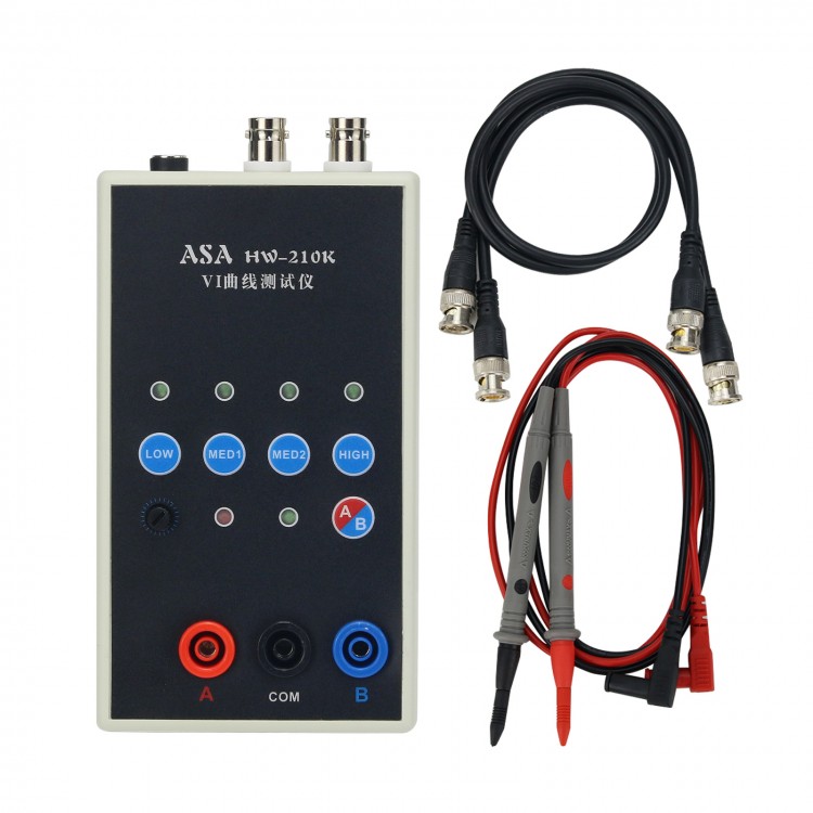


 Shows Four Test Frequencies")
 Shows Four Test Frequencies")

 Shows Four Test Frequencies")
 Shows Four Test Frequencies")

