| Quantity | 3+ units | 10+ units | 30+ units | 50+ units | More |
|---|---|---|---|---|---|
| Price /Unit | $46.25 | $45.30 | $43.89 | $42.00 | Contact US |
 SUP-C703S Signal Generator & Process Calibrator – mA, V, Ω, RTD, Thermocouple Output & Measurement
$156.44
SUP-C703S Signal Generator & Process Calibrator – mA, V, Ω, RTD, Thermocouple Output & Measurement
$156.44
 6000A 20µH Air Core Inductor for Dual Pulse Testing and High-Performance Electrical Experiments
$86.76
6000A 20µH Air Core Inductor for Dual Pulse Testing and High-Performance Electrical Experiments
$86.76
 DP8000 Max IGBT Pulse Generator with Internally Integrated IGBT Driver (Air Core Inductor Included)
$384.16
DP8000 Max IGBT Pulse Generator with Internally Integrated IGBT Driver (Air Core Inductor Included)
$384.16
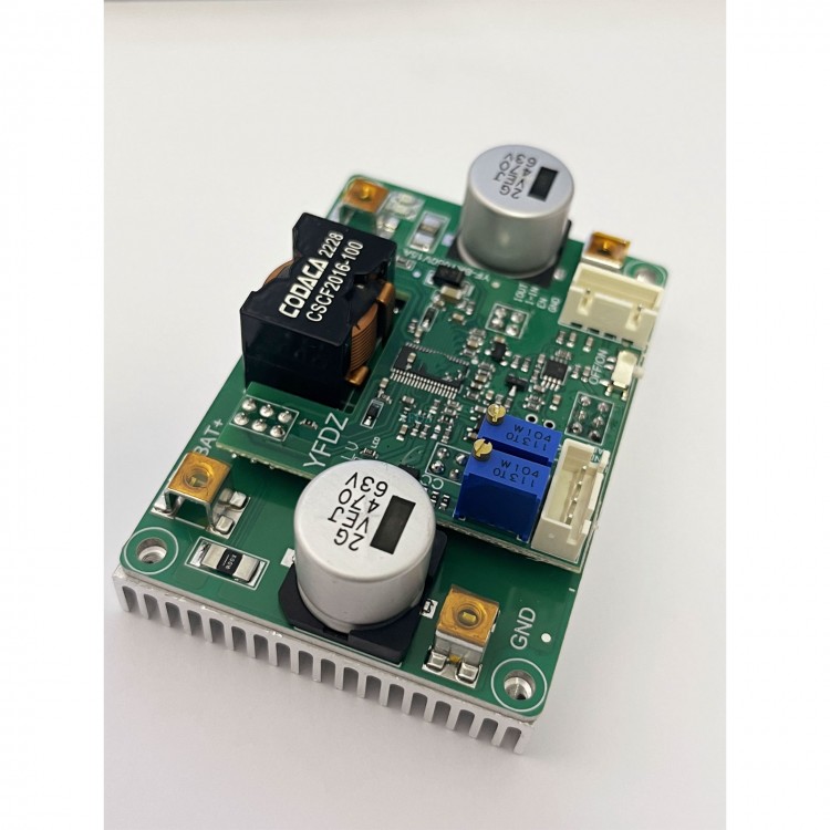
YF-BKT050V15A 0.5-15A/3-52V Step up down Converter Buck Boost Converter Board with Heat Sink
Read before purchasing:
- Do not use a 3A/5A regulated DC power supply as an input to test the power supply.
- Basic technical knowledge and hands-on ability are highly recommended.
- Users need to modify parameters such as undervoltage protection parameters. We can tell you how to modify it.
-
The power supply is very stable and can be used for 5000h on the
average without failure. Factors, such as reverse connection, water
ingress, corrosion, over-voltage, over-temperature and control
modification errors will get it damaged.
- Certain power supply test
and measurement capabilities and equipment are recommended. Do not test
this power supply with a 3A adjustable regulated power supply used in
labs.
- Do not test the current-limiting power supply in CC mode of an electronic load.
-
Output current adjustment range: If the input power is sufficient, and
the output power supply is 20V and a 0.4Ω resistor is connected to
adjust CC potentiometer, the output current can be adjusted to a maximum
of 20A, but cannot be adjusted to the minimum limit value (except 0A).
Features:
- Ultra-cost-effective buck-boost power supply
- Stable performance, high efficiency and small size
- Designed with aluminum substrate
Package Included:
- 1 x Power supply board with heat sink
Note:
- Battery is not included.
Typical Performance:
- Non-isolated four-switch synchronous buck-boost
- Wide input DC10-52V, output DC3-50V
- Peak efficiency >98.5%
- Input over-voltage, output short-circuit protection self-recovery
- Reverse protection (input fuse)
- Over-temperature protection, remote ON/OFF
- Input and output current signal interface
- Output voltage, current control interface
- Accurate and stable output current regulation
- Battery charge back-charge protection to 53V
- Super capacitor 0V voltage constant current charging
- With load indicator light, shutdown input and output are completely disconnected
- Low quiescent current, fast dynamic response, and power can be over 500W (input and output> 36V)
- Aluminum substrate, high thermal conductivity, 90°C normal operation
-
All tests are made at 24V input voltage, resistive load, and 25°C room
temperature. Parameters are subject to change without notice
Attention:
1:
Please calculate whether the maximum load is suitable according to
Iout=VIN*Iin*(0.92-0.98)/Vout. The parameter range should be within the
value of the table. Iin (max) = 20A is suitable for all parameter
calculations. For example, Vin=12V, Vout=24V, Iout=10A. Vin=48V,
Vout=24V, then Iout can be more than 15A.
2: The ripple current of
the boost output capacitor is large, and the ripple current of the
step-down input capacitor is large, which reduces the capacitor heating
and prolongs the life. Electrolytic capacitors can be connected in
parallel.
3: Can be directly connected to battery for charging. It is
recommended to adjust the output voltage correctly before connecting
the target battery.
4: The slow startup time and EN enable together
to control the delay time. When the start-up time of the input source is
long, you need to adjust the slow startup time of the output. For
example, the AC adaptation output full-load voltage settling time is
50ms, while the power supply startup time is 2ms, which may cause AC to
fail to start properly with load.
5: Users with dynamic response
requirements can optimize specifically. For example, the output is
connected to sensitive devices such as a host computer.
6: Some parameters may be adjusted for different applications.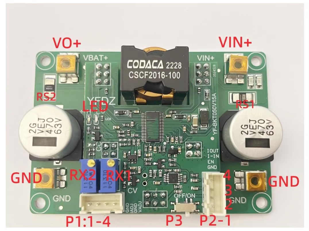
Attention:
1:
When testing this power supply, it must be ensured that the input
source can provide a large enough current (>25A) to ensure that the
power supply does not collapse or even be damaged, especially when
starting with load. When the live test is performed, the negative
electrode is connected first, and then connect the positive electrode.
When shutting down, disconnect the positive terminal first.
2: The
startup time of the input source must be less than the startup time of
this power supply (e.g. adapter as input), otherwise it may not be
possible to start with load.
3: The input wire connected to this
power supply shall not be too long (the internal resistance of the wire
shall not be too large), otherwise the power supply may cause
oscillation and abnormality.
4: If there is a diode in series with
the input source to this power supply, the power supply may be damaged
by the surge voltage caused by instantaneous on-off (line BOOST effect).
5:
Do not use the CC mode of an electronic load as the load of this power
supply. It is recommended to use the CR mode. CC mode draws current,
this power supply is current limited, and in constant current mode, this
will cause the power supply to crash.
6: It is recommended to
connect adjustable output voltage with a resistive load (dummy load)
with small current, to ensure the real-time adjustment of output voltage
potentiometer. Otherwise, the output voltage will change slowly and the
regulation will be inaccurate.
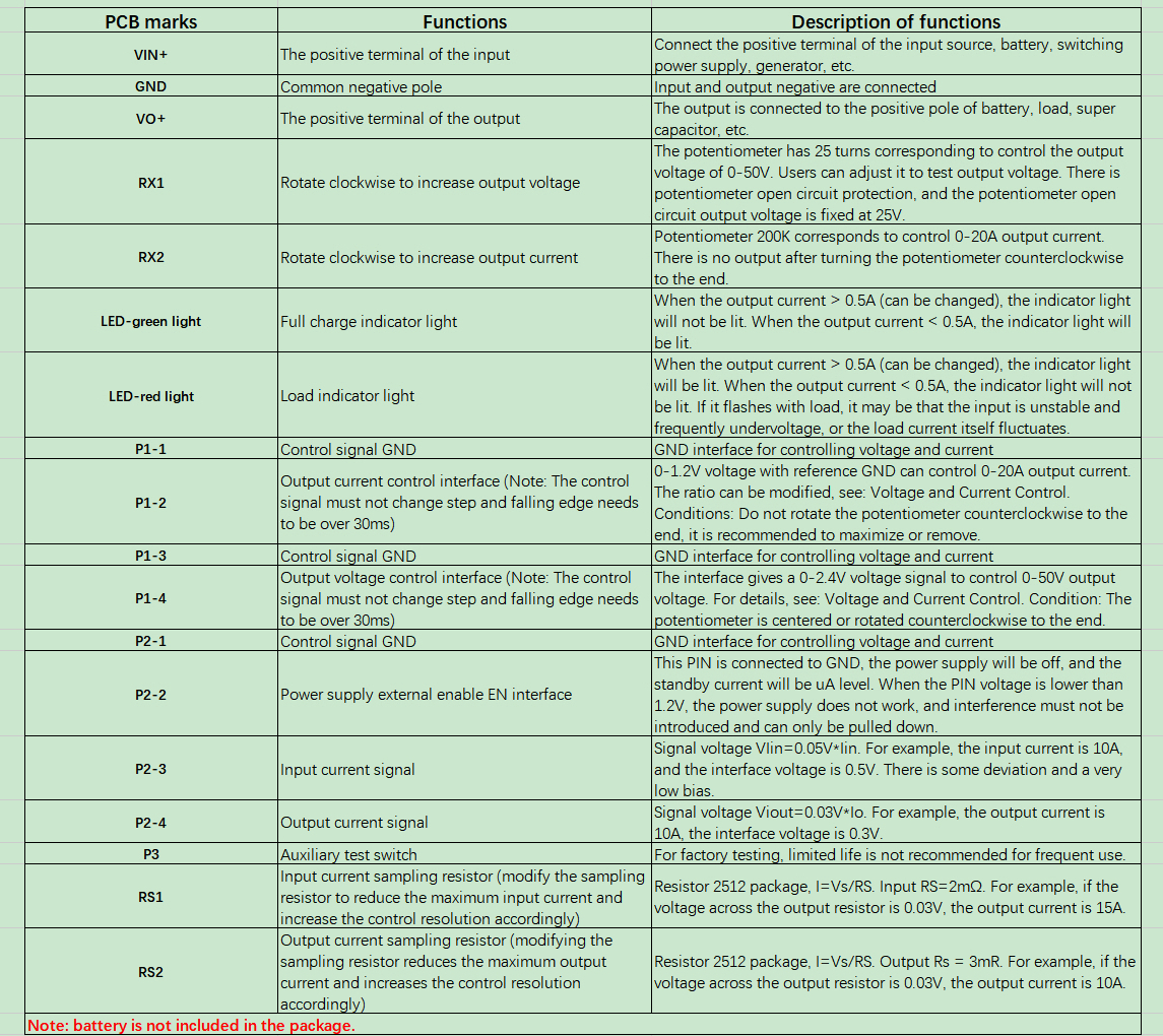
Modify input undervoltage protection value:
The
default undervoltage protection value is V=(R1/R2+1)*1.2=9.0V (R1=130K,
R2=20K). By modifying the two resistor values, you can modify the input
undervoltage protection value. Note: Undervoltage protection must have a
hysteresis range, which cannot be changed. The input current and the
diameter of the wire affect the protection value. It is recommended to
set the value a little lower.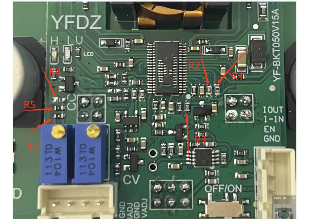
Voltage and Current Control:
1:
Voltage control Vo=52.8-21.5*Vx. Vx is the voltage of the external
control signal (0-2.4V), and the voltage control signal must not have
step change, otherwise it may cause permanent damage to the board.
2:
Current control: Iout=Vi/0.06. Vi is the external control signal
voltage (0-1.2V). For example, if the no-load signal is 0.6V, the output
current is limited to 10A ± 0.3A. It is recommended to correct the
scale.
If the load capacity of the control signal is not enough,
R3 can be removed. R6 can be completely externally controlled. Without
giving a control signal, there will be no output. If the ratio cannot
reach 0-1.2V, R3 and R6 can be removed.
R5 and R4 are divided by
voltage, for example, R5=80K, R4=20K, then the control signal becomes
0-6V corresponding to controlling output current of 0-20A (amplified by 5
times)
Attention: Step change is not allowed for the control signal, otherwise it may cause permanent damage to the board.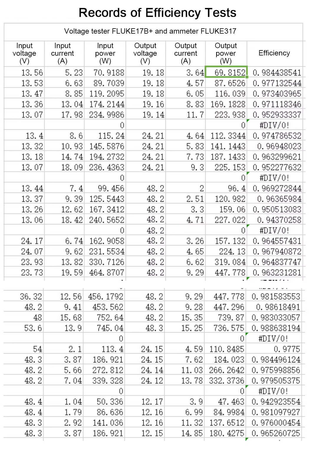
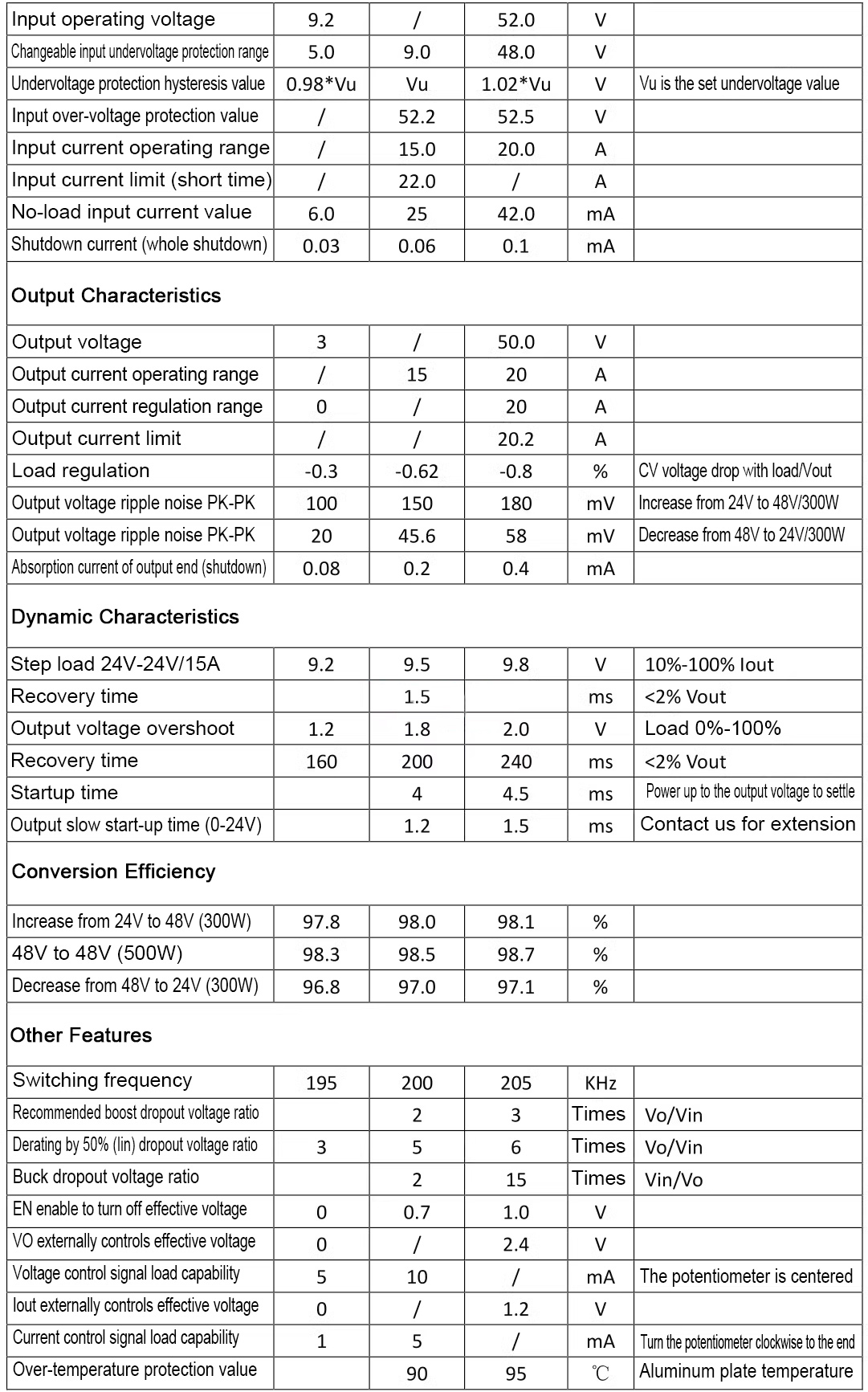
The
above efficiency data is the actual test value, and the efficiency
range is 94.2-98.8%. You can refer to the above data to estimate the
efficiency of your own application parameters.